A belt conveyor
A technology of belt conveyors and racks, applied in the directions of conveyors, conveyor objects, transportation and packaging, etc., can solve the problems of increasing the rotational workload of the transmission rollers, reducing the effective transmission volume, and damage to the conveyor belt, avoiding transmission The effect of reducing efficiency, improving work stability, and increasing service life
- Summary
- Abstract
- Description
- Claims
- Application Information
AI Technical Summary
Problems solved by technology
Method used
Image
Examples
Embodiment 1
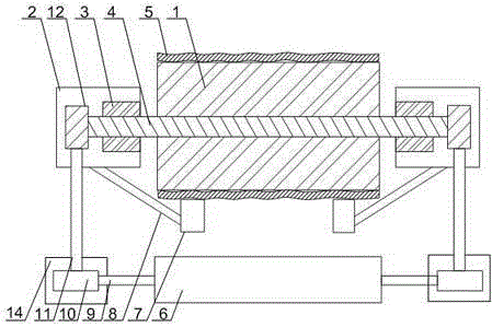
[0025] like Figure 1 to Figure 3As shown, a belt conveyor of the present invention includes a frame and a conveyor belt, on which a main roller 1, a driven roller 16 and a support cylinder 2 are arranged, and a conveyor belt 5 is sleeved on the main roller 1 and the driven roller 16, the rotating shaft 4 of the main drum 1 runs through one end of the supporting cylinder 2 and is rotated in the bearing 3, and the rotating shaft 4 is connected with the cylinder knife 6 parallel to the rotating shaft 4 through an interlocking mechanism; it also includes a V-shaped blade 7, so The V-shaped blade 7 is fixed on the support cylinder 2 through a connecting rod 8. The V-shaped blade 7 is in the shape of a circular arc matched with the outer surface of the main drum 1, and a roller 13 is installed on the intersection of the V-shaped blade 7. 13 is in contact with the conveyor belt 5 on the main drum 1, and a tensioning mechanism is installed on the driven drum 16. When the present inv...
Embodiment 2
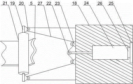
[0027] like image 3 As shown, on the basis of Embodiment 1, the present embodiment includes an adjustment platform 18, a support rod 19 and a pulling wire 27, and a roller 21 is rotated on the support rod 19, and at both ends of the support rod 19 A pulley 20 is installed, and the adjustment platform 18 is connected with the support rod 19 through the pulley 27 through the pulley 27. Cylinder 24 and baffle plate 25, pressure sensor 26 is installed between the tail end of cylinder 24 and baffle plate 25, and pressure sensor 26 is connected with the driving device of cylinder 24 by wire, on the flexible end of cylinder 24, rotating Wheel 22, runner 22 is connected with traction line 27, and traction line 27 is in tight state all the time during work. During work, the roller 21 is in contact with the non-transmitting surface of the conveyor belt 5, and the runner 22 cooperates with the pulley 20 through the traction line 27, so that the output end of the cylinder 24 is always s...
Embodiment 3
[0029] like figure 1 As shown, this embodiment is based on Embodiment 1, the interlocking structure includes a connecting rod 11, a large gear 12 and a pinion 10, the two ends of the rotating shaft 4 pass through the bearing 3, and the large gear 12 is installed on the rotating shaft 4 At both ends of the central axis 9 of the cylinder cutter 6, a protective cylinder 14 is installed, and a pinion 10 is arranged in the protective cylinder 14, and the end of the central axis 9 penetrates one side of the protective cylinder 14 and is connected with the pinion 10, so The two ends of the connecting rod 11 are equipped with racks, and the large gear 12 cooperates with the pinion 10 through the connecting rod 11 . The rotating shaft 4 rotates, and under the cooperation of the large gear 12, the pinion 10 and the connecting rod 11, the central shaft 9 will drive the cylinder knife 6 and the transmission drum 1 to rotate synchronously, so as to ensure that the cylinder knife 6 contacts...
PUM
 Abstract
Description
Claims
Application Information
 - R&D
- Intellectual Property
- Life Sciences
- Materials
- Tech Scout
- Unparalleled Data Quality
- Higher Quality Content
- 60% Fewer Hallucinations
Browse by: Latest US Patents, China's latest patents, Technical Efficacy Thesaurus, Application Domain, Technology Topic, Popular Technical Reports.
© 2025 PatSnap. All rights reserved.Legal|Privacy policy|Modern Slavery Act Transparency Statement|Sitemap|About US| Contact US: help@patsnap.com


