Disconnect Switches, Pressure Switch Assemblies, and Pressure Cookers

A technology of a pressure switch and a power-off switch, which is applied in the field of pressure cookers, can solve the problems of inconvenient use, poor practicability, and abnormal tripping of the power-off switch, etc., and achieves controllable and adjustable, good practicability, and improved The effect of using security

Inactive Publication Date: 2016-02-03
FOSHAN SHUNDE MIDEA ELECTRICAL HEATING APPLIANCES MFG CO LTD +1
View PDF8 Cites 0 Cited by
  • Summary
  • Abstract
  • Description
  • Claims
  • Application Information

AI Technical Summary

Problems solved by technology

[0002] When the pressure cooker is working, it will cause pressure release when the pressure switch fails. In order to realize its safety, it is necessary to cut off the heating power supply before the pressure release, so as to realize the power-off protection before the pressure release; the scheme adopted by the related technology is, An additional power-off switch is added to the pressure switch to provide secondary protection for the pressure cooker, that is, to cut off the power-off switch when the pressure switch fails, so as to realize the power-off protection before the pressure cooker is released, through the pressure switch and power-off The purpose of double protection of the pressure cooker is achieved by the cooperation of the switch; however, the existing power-off switches all realize the power-off function through the signal induction principle of electronic components (rather than through the mechanical structure to realize the power-off action). During use, the power switch is very prone to abnormal tripping, which leads to its poor practicability and brings a lot of inconvenience to users.

Method used


Image

  • Disconnect Switches, Pressure Switch Assemblies, and Pressure Cookers
  • Disconnect Switches, Pressure Switch Assemblies, and Pressure Cookers
  • Disconnect Switches, Pressure Switch Assemblies, and Pressure Cookers

Examples


Embodiment Construction

[0029] In order to understand the above-mentioned purpose, features and advantages of the present invention more clearly, the present invention will be further described in detail below in conjunction with the accompanying drawings and specific embodiments. It should be noted that, in the case of no conflict, the embodiments of the present application and the features in the embodiments can be combined with each other.

[0030] In the following description, many specific details are set forth in order to fully understand the present invention. However, the present invention can also be implemented in other ways than described here. Therefore, the protection scope of the present invention is not limited by the specific implementation disclosed below. Example limitations.

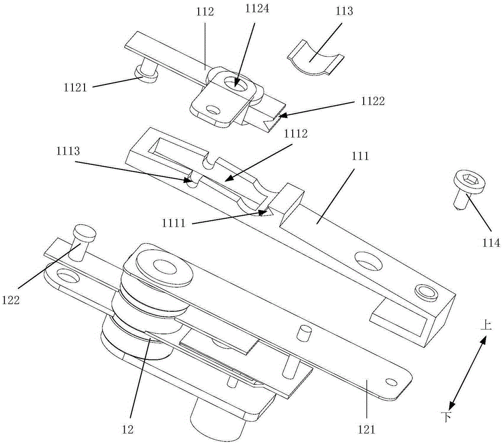
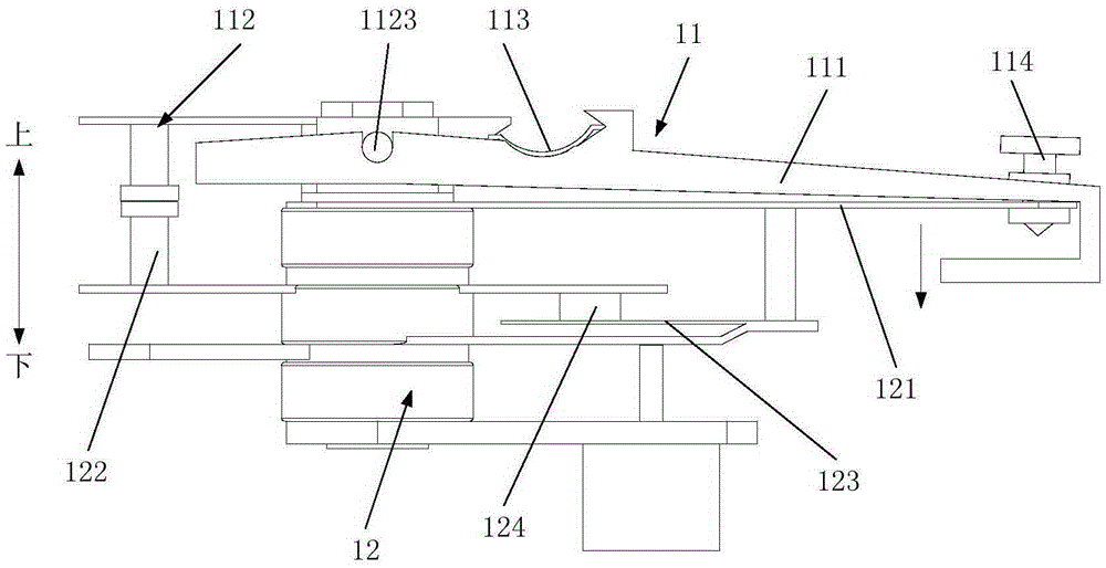
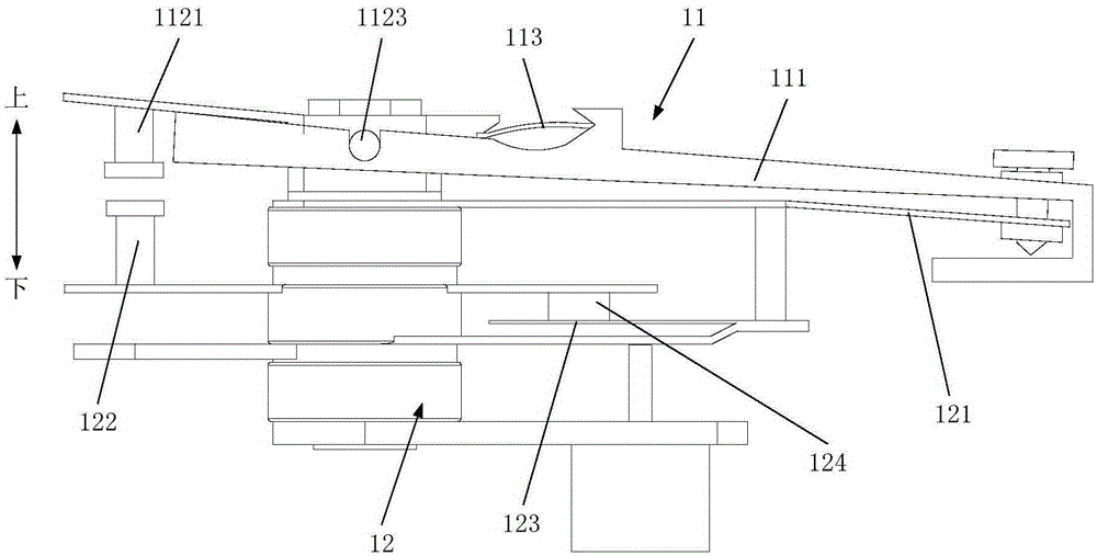
[0031] Such as Figure 1 to Figure 3 As shown, the cut-off switch 11 provided by the present invention is used to cooperate with the pressure switch 12, and includes a strut 111, a contact 112 and a sudden c...


PUM


Abstract

The invention provides a power outage switch, a pressure switch assembly and a pressure cooker. The power outage switch is used in cooperation with a pressure switch, the pressure switch assembly comprises fulcrum bars, a contact piece and an abrupt change piece, the fulcrum bars and the contact piece are located on the upper portion of the pressure switch and installed on the pressure switch in a rotatable mode, one of the ends, away from the contact piece, of the fulcrum bars is connected with an elastic piece of the pressure switch, the other of the ends, away from the contact piece, of the fulcrum bars makes contact with a contact of the pressure switch, and the abrupt change piece is arranged between the ends, close to the contact piece, of the fulcrum bars. The power outage switch is simple in structure and convenient to assemble and can be adjusted in a controllable mode by selecting different abrupt change pieces and screwing screws by different depths, namely, the maximum value of pressure which the pressure switch can bear in an abnormal state can be set autonomously, when the pressure borne by the pressure switch reaches the pressure value set autonomously, the power outage switch jumps to disconnect the power source of the pressure switch, and therefore the pressure in the jump disconnection process is controllable and adjustable.

Description

technical field [0001] The present invention relates to the field of household appliances, and more specifically relates to a power cutoff switch, a pressure switch assembly including the power cutoff switch, and a pressure cooker including the pressure switch assembly. Background technique [0002] When the pressure cooker is working, it will cause pressure release when the pressure switch fails. In order to realize its safety, it is necessary to cut off the heating power supply before the pressure release, so as to realize the power-off protection before the pressure release; the scheme adopted by the related technology is, An additional power-off switch is added to the pressure switch to provide secondary protection for the pressure cooker, that is, to cut off the power-off switch when the pressure switch fails, so as to realize the power-off protection before the pressure cooker is released, through the pressure switch and power-off The purpose of double protection of th...

Claims


Application Information

Patent Timeline
Patent Type & Authority Patents(China)
IPC IPC(8): H01H35/26A47J27/09
Inventor 魏俊波
Owner FOSHAN SHUNDE MIDEA ELECTRICAL HEATING APPLIANCES MFG CO LTD
Why Eureka
Try Eureka