
Data transmission system

A data transmission system and data technology, applied in the field of data transmission, can solve the problems of high cost, high network construction cost and operation cost, and low data collection efficiency.

Inactive Publication Date: 2014-08-13
SHENZHEN ENVIRONMENTAL MONITORING CENT
View PDF6 Cites 13 Cited by
  • Summary
  • Abstract
  • Description
  • Claims
  • Application Information

AI Technical Summary

Problems solved by technology

[0003] At present, there are two data transmission methods in the above-mentioned fields. The first one is to rely on the mobile operator's wireless communication network for data transmission, for example, using the mobile operator's satellite positioning service, GSM network, CDMA network, 3G network, FDMA network, etc. , TDMA network, fixed wireless access or wireless local area network for data transmission, but this transmission method requires long-term payment of high data traffic fees, which makes the input cost high; the second is to use wired network transmission and build base stations at the location where transmission is required. Then use twisted pair, coaxial cable or optical fiber for data transmission, but the transmission party needs to pay high network construction costs and long-term operating costs, which also makes the input cost high
[0004] In addition, for areas such as mountainous areas, forests, oceans, and lakes, it is impossible to build wired networks, or even have no wireless network coverage. The above two methods cannot realize data transmission. Only professionals can use portable instruments to monitor and monitor point by point. way to bring back data
However, this data transmission method has low data collection efficiency, and because it requires manual real-time monitoring and data collection, it also requires high cost

Method used


Image

  • Data transmission system
  • Data transmission system
  • Data transmission system

Examples


Embodiment Construction

[0035] In order to make the purpose, technical solutions and advantages of the embodiments of the present invention clearer, the technical solutions in the embodiments of the present invention will be clearly and completely described below in conjunction with the drawings in the embodiments of the present invention. Obviously, the described embodiments It is a part of embodiments of the present invention, but not all embodiments. Based on the embodiments of the present invention, all other embodiments obtained by persons of ordinary skill in the art without making creative efforts belong to the protection scope of the present invention.

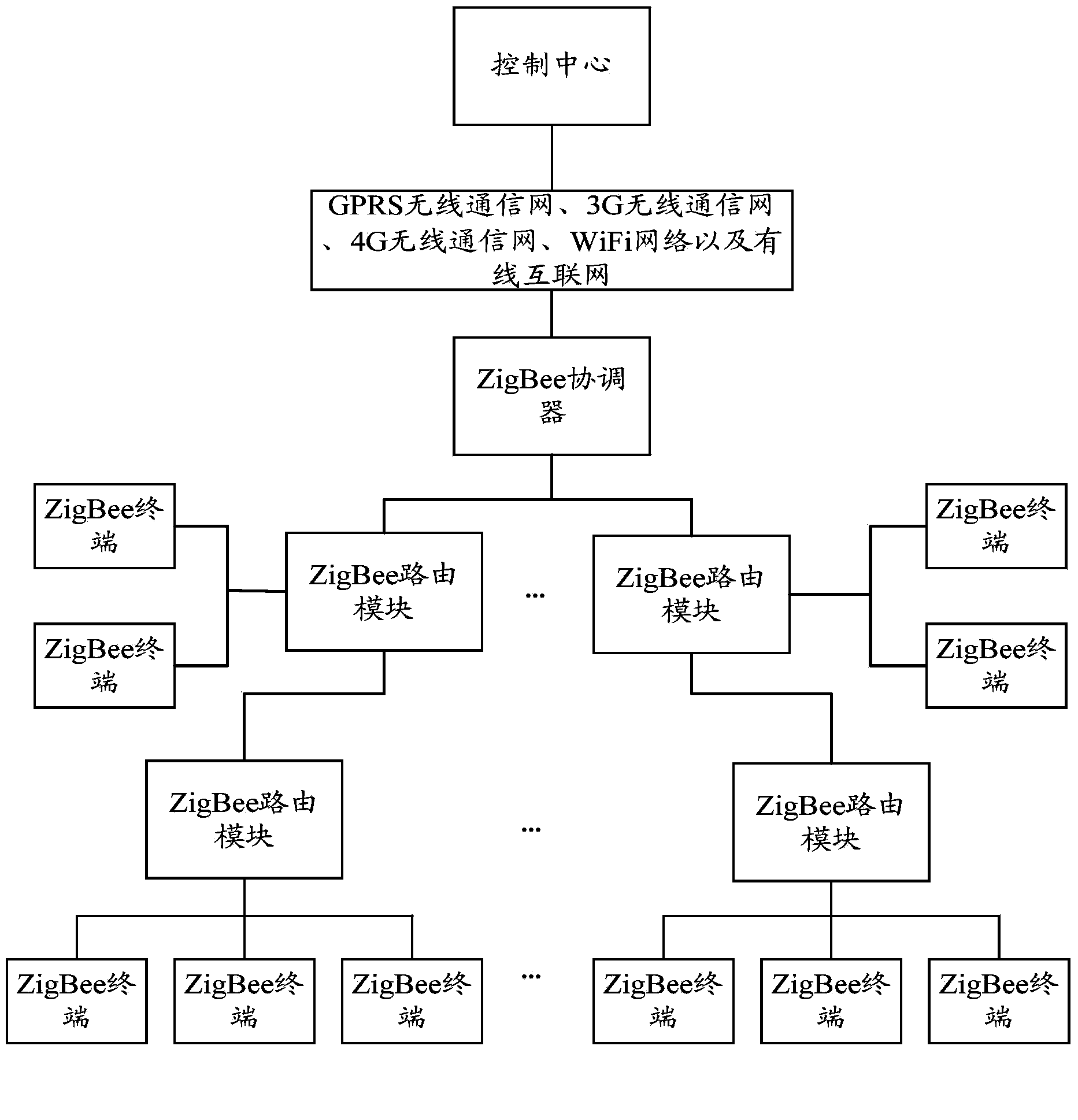
[0036] To facilitate the understanding of this embodiment, first, a brief description is given of the data transmission system based on this embodiment. Such as figure 1 As shown, the data transmission system involved in the present invention includes: at least one ZigBee coordinator 11 with gateway function and a plurality of cascaded ZigBe...


PUM


Abstract

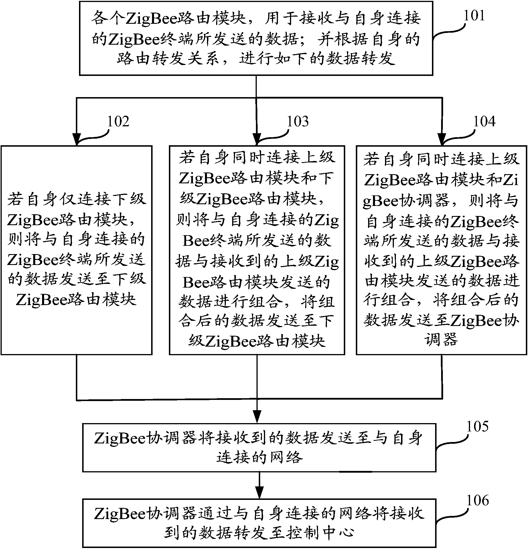
The invention provides a data transmission system which comprises a ZigBee coordinator and multiple cascaded ZigBee routing modules, wherein the ZigBee routing modules are used for receiving data sent by ZigBee terminals connected with the corresponding ZigBee routing modules and independently sending the data of the ZigBee terminals or combining the received data of other ZigBee routing modules and then sending the combined data to a ZigBee network consisting of the ZigBee routing modules at the higher level; the ZigBee routing modules are connected with a GPRS (general packet radio service) wireless communication network, a 3G (third generation) wireless communication network, a 4G (fourth-generation) wireless communication network, a WiFi (wireless fidelity) network or a wired internet to realize remote data transmission. The ZigBee network construction in the data transmission system is low in complexity and low in cost, can be subjected to hybrid networking with the wireless communication network, the WiFi and the wired internet to realize remote, low-cost and wide large data transmission, is high in data transmission efficiency, and is high in stability and reliability.

Description

technical field [0001] The present invention relates to the field of data transmission, in particular to a data transmission system. Background technique [0002] With the rapid development of electronic technology and computer technology, the demand for data in the fields of environmental protection, agricultural production, public safety, medical monitoring, fire safety, transportation, etc. is also increasing, showing a geometric progression. [0003] At present, there are two data transmission methods in the above-mentioned fields. The first one is to rely on the mobile operator's wireless communication network for data transmission, for example, using the mobile operator's satellite positioning service, GSM network, CDMA network, 3G network, FDMA network, etc. , TDMA network, fixed wireless access or wireless local area network for data transmission, but this transmission method requires long-term payment of high data traffic fees, which makes the input cost high; the s...

Claims


Application Information

Patent Timeline
IPC IPC(8): H04W16/26H04W40/24H04W84/18
Inventor 郭键锋王东黄恒时劲松张金帆
Owner SHENZHEN ENVIRONMENTAL MONITORING CENT
Learn More