Electric power cable shearing device

A technology for a power cable and a cutting device, which is applied in the field of power equipment, can solve the problems of high hardness of the power cable or steel wire, inconvenient construction and operation, inconvenient cutting, etc., and achieves the effects of being convenient to carry, convenient for replacement and maintenance, and convenient for operation.

Inactive Publication Date: 2014-08-20
STATE GRID CORP OF CHINA +1
View PDF5 Cites 2 Cited by
  • Summary
  • Abstract
  • Description
  • Claims
  • Application Information

AI Technical Summary

Problems solved by technology

[0002] In order to facilitate the cutting of power cables or steel wires during construction, workers often need to carry wire cutting tools. Traditional wire cutting tools mostly use manpower as the power for cutting wires. Because many power cables or steel wires are very hard, it is very difficult to easy to cut
Moreover, in order to cut power cables with relatively large diameters, workers need to carry large wire cutting tools, which is very inconvenient for construction operations in the field and other occasions

Method used


Image

  • Electric power cable shearing device
  • Electric power cable shearing device

Examples


Embodiment 1

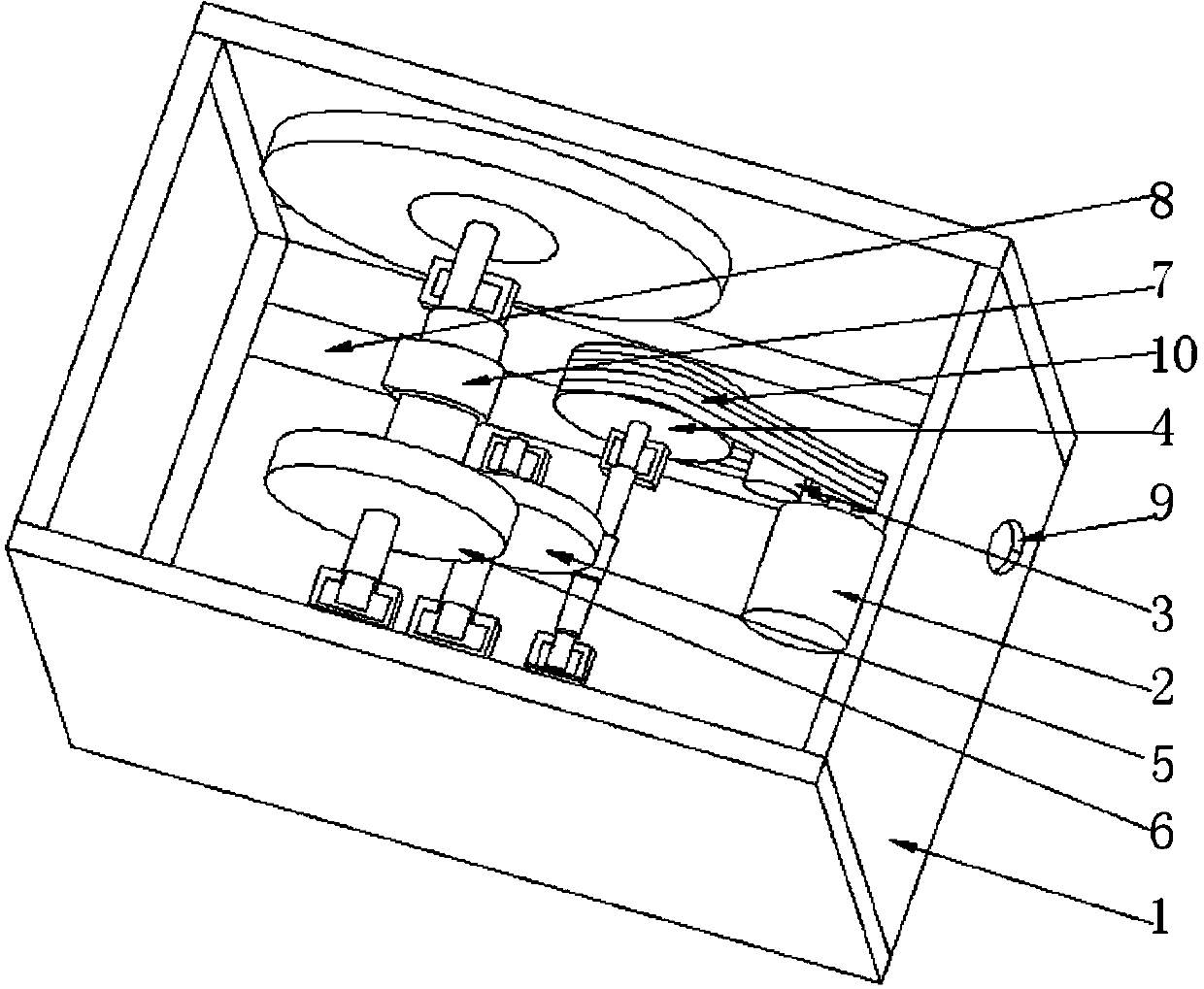
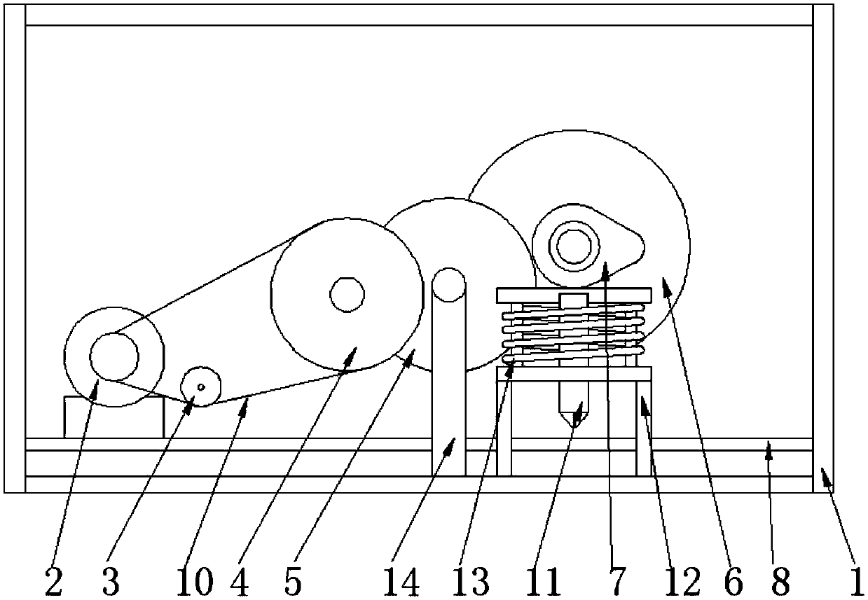
[0024] Such as figure 1 , figure 2 As shown, an electric power cable cutting device is mainly composed of a motor 1, a driven wheel 4, a small flywheel 5, a large flywheel 6, a cam 7, a cutter 11, and a cutter bracket 12. Between the motor 1 and the driven wheel 4 Connected by transmission belt 10, gears are provided on the shaft where the driven wheel 4 is located, and the small flywheel 5 is meshed with the gear on the shaft of the driven wheel 4, and gears are provided on the shaft where the small flywheel 5 is located, so The gear on the big flywheel 6 is meshed with the small flywheel 5 shaft, the cam 7 is located on the shaft where the big flywheel 6 is located, the upper end of the cutter 11 is connected with the upper part of the cutter holder 12, and the cutter holder 12 is located below the cam 7 , the tool holder 12 is provided with a spring 13 . When needed, the staff can place the power cable to be cut under the cutter, start the motor 2, and drive the driven w...

Embodiment 2

[0026] In order to better realize the present invention and facilitate adjustment of the tightness of the belt 10 , this embodiment further includes a tensioning wheel 3 on the basis of the first embodiment, and the tensioning wheel is located inside the belt 10 on the side close to the motor 2 . By setting the tensioning pulley 3, the tension force of the belt can be adjusted, so that the transmission system is stable, safe and reliable. Other parts of this embodiment are the same as those of Embodiment 1, and will not be repeated here.

Embodiment 3

[0028] In order to better realize the present invention and facilitate the control of the trajectory of the power cable, this embodiment further includes a chute 8 on the basis of the embodiment 2, and the chute 8 is located below the cutter 11 . By setting the chute 8, the power cable can be placed inside the chute 8 for cutting operation, so as to prevent the power cable from being difficult to organize during the cutting process. Other parts of this embodiment are the same as those of Embodiment 2, and will not be repeated here.


PUM


Abstract

The invention discloses an electric power cable shearing device which is mainly formed by a motor, a driven wheel, a small flywheel, a large flywheel, a cam, a cutter and a cutter support. The motor is connected with the driven wheel through a transmission belt, a gear is arranged on a shaft where the driven wheel is located, the small flywheel is meshed with the gear on the driven wheel shaft, a gear is arranged on a shaft where the small flywheel is located, the large flywheel is meshed with the gear on the small flywheel shaft, the cam is located on a shaft where the large flywheel is located, the upper end of the cutter is connected with the upper portion of the cutter support, the cutter support is located below the cam, and a spring is arranged on the cutter support. By means of the electric power cable shearing device, the cam is driven by the motor to rotate to eject the cutter to regularly shear a cable, physical power consumption is not needed, and the electric power cable shearing device is simple in structure and convenient to carry.

Description

technical field [0001] The electric power equipment field of the present invention specifically refers to an electric power cable cutting device. Background technique [0002] In order to facilitate the cutting of power cables or steel wires during construction, workers often need to carry wire cutting tools. Traditional wire cutting tools mostly use manpower as the power for cutting wires. Because many power cables or steel wires are very hard, it is very difficult to Easy to cut. Moreover, in order to cut power cables with relatively large diameters, workers need to carry large wire cutting tools, which is very inconvenient for construction operations in the field and other occasions. Contents of the invention [0003] The purpose of the present invention is to provide an electric power cable cutting device, which can overcome the above-mentioned defects, and use the motor to drive the cam to rotate the pushing tool to cut the cables regularly without consuming physical...

Claims


Application Information

Patent Timeline
IPC IPC(8): B21F11/00
Inventor 张志毕世兵
Owner STATE GRID CORP OF CHINA
Why Eureka
Try Eureka