Eureka AIR delivers breakthrough ideas for toughest innovation challenges, trusted by R&D personnel around the world.

Wheel sprue drilling device

A wheel and drilling technology, applied in the field of drilling devices, can solve the problems of internal tissue damage, high labor intensity and low efficiency, and achieve the effects of high degree of automation, simple structure and advanced technology

Inactive Publication Date: 2014-08-20
CITIC DICASTAL
View PDF6 Cites 6 Cited by
  • Summary
  • Abstract
  • Description
  • Claims
  • Application Information

AI Technical Summary

Problems solved by technology

This method is not only inefficient, but also labor-intensive for workers; another method is to use special equipment to stamp and remove it online. Although this method has high efficiency, it is easy to cause damage to the internal tissue near the gate during the stamping process. , however large wheel manufacturers are gradually phasing it out

Method used


Image

  • Wheel sprue drilling device
  • Wheel sprue drilling device
  • Wheel sprue drilling device

Examples


Embodiment Construction

[0016] The details and working conditions of the specific device proposed according to the present invention will be described below in conjunction with the drawings.

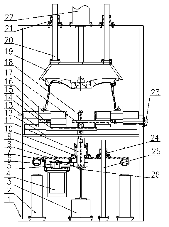
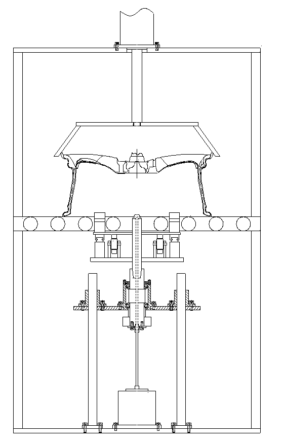
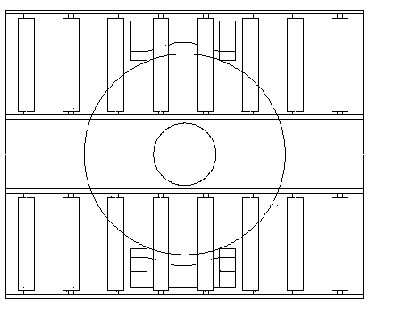
[0017] Wheel gate drilling device, consisting of frame 1, hydraulic cylinder 2, oil mist generator 3, motor 4, flange 5, pulley Ⅰ 6, pulley Ⅱ 7, timing belt 8, lifting plate 9, bearing seat 10, hollow Drill clamp 11, connecting plate 12, guide rail 13, rack 14, sliding plate 15, clamping block 16, gear 17, internal cooling drill bit 18, clamp 19, guide post Ⅰ 20, guide sleeve Ⅰ 21, cylinder Ⅰ 22, cylinder Ⅱ 23, guide sleeve Ⅱ 24 , Guide column Ⅱ 25 and rotary joint 26. Two hydraulic cylinders 2, an oil mist generator 3 and four guide posts Ⅱ25 are fixed at the bottom of the frame 1; the output rods of the two hydraulic cylinders 2 are hinged with the lifting plate 9, and the upper end of the lifting plate 9 is fixed with bearing seats 10 and four A guide sleeve Ⅱ24 is fixed with a motor 4 through a flange 5 at th...


PUM


Abstract

The invention discloses a wheel sprue drilling device. The wheel sprue drilling device is composed of a machine frame, a fixture, an oil fog generator, a hydraulic cylinder, air cylinders and the like. When the wheel sprue drilling device is used, a wheel is positioned through a sensor, clamping blocks clamp the lower rim of the wheel through a gear rack and the second air cylinder, the first air cylinder presses the fixture to the upper rim of the wheel through a first guide column, the hydraulic cylinder lifts a motor and an inner-cooling drill bit through a second guide column, the motor drives the inner-cooling drill bit to rotate through a synchronous belt, and when the inner-cooling drill bit makes contact with a diversion taper hole, the inner-cooling drill bit drills a wheel sprue based on the guiding function of the inner-cooling drill bit. When the wheel sprue drilling device is used, on-line drilling removing can be carried out in the wheel sprue on the lower portion, the technology is advanced, and the wheel sprue drilling device has the advantages of being simple in structure, safe and stable in performance, high in automation degree and the like.

Description

Technical field [0001] The invention relates to a drilling device. Background technique [0002] In manufacturers of aluminum alloy wheels, the gates formed after casting are often manually clamped on the drill press fixture beside the roller table one by one, and then removed by drilling. This method is not only inefficient, but also labor-intensive. Another method is to use special equipment to punch and remove. Although this method is efficient, it is easy to cause damage to the internal organization near the gate during the punching process. However, large wheel manufacturers are gradually eliminating them. The device effectively realizes the online drilling and removal of the wheel gate, not only the technology is advanced, but also the efficiency is high. Summary of the invention [0003] The purpose of the present invention is to provide a wheel gate drilling device, which can realize on-line drilling and removal of the wheel blank gate. [0004] In order to achieve the ab...

Claims


Application Information

Patent Timeline
Patent Type & Authority Applications(China)
IPC IPC(8): B22D31/00
Inventor 薛博文郭建东刘会莹王永宁朱志华李昌海
Owner CITIC DICASTAL
Why Eureka
Eureka Blog
Learn More