
Gantry fragment discharging mechanism

A gantry and chip flute technology, used in metal processing machinery parts, maintenance and safety accessories, metal processing equipment, etc., can solve the problems of reducing production efficiency and improving the labor intensity of operators, so as to improve efficiency and improve stability and reliability. , the effect of simple structure

Active Publication Date: 2014-08-20
宁波川田精密机械有限公司
View PDF9 Cites 12 Cited by
  • Summary
  • Abstract
  • Description
  • Claims
  • Application Information

AI Technical Summary

Problems solved by technology

The disadvantage of this invention is that the planer milling machine still cleans up the debris by manual operation, which greatly improves the labor intensity of the operator and reduces the production efficiency

Method used


Image

  • Gantry fragment discharging mechanism
  • Gantry fragment discharging mechanism
  • Gantry fragment discharging mechanism

Examples


Embodiment Construction

[0019] The present invention will be further described below in conjunction with the accompanying drawings and specific embodiments.

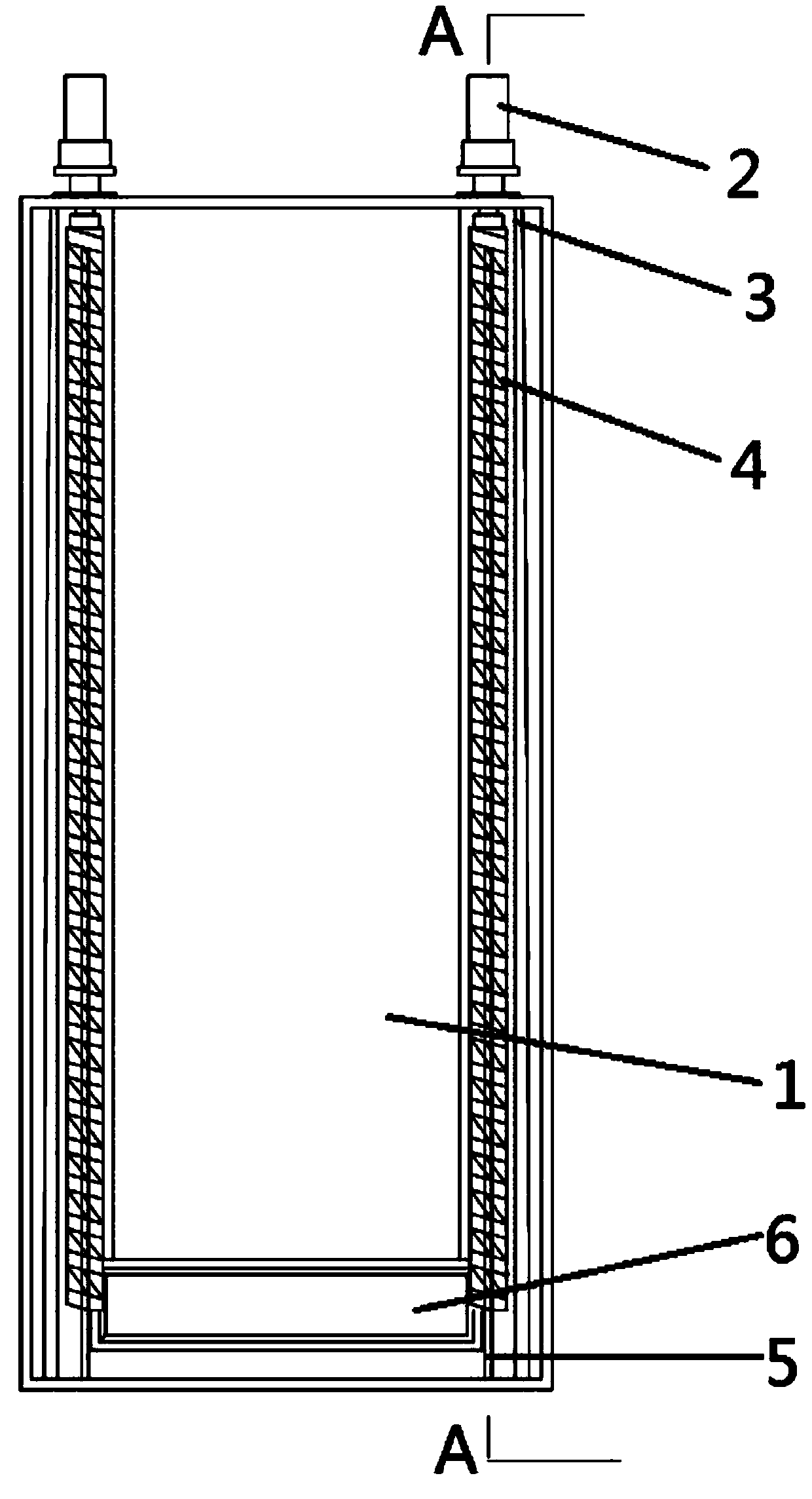
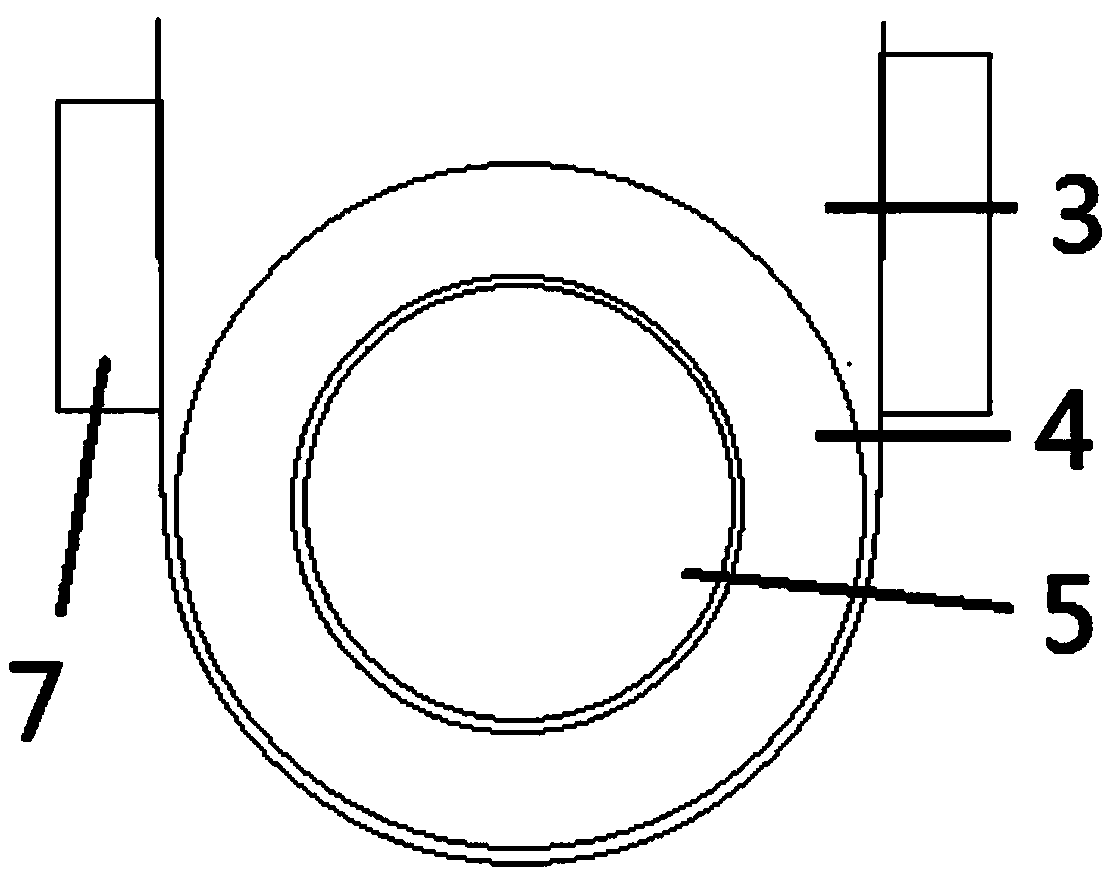
[0020] Such as figure 1 , figure 2 , image 3 In the described embodiment, a gantry chip removal mechanism is installed on the gantry bed 1 and includes a chip removal groove 3 and a chip removal device. The cross section of the chip removal groove 3 is U-shaped, and the chip removal mechanism The bottom of the groove 3 is arc-shaped, and there are two chip removal grooves 3, which are respectively placed on both sides of the gantry bed 1. The chip remover includes a motor 2 and a chip removal rod 4. The motor 2 is installed on the gantry bed 1. The chip removal rod 4 is installed in the chip removal groove 3, the shape of the chip removal rod 4 is spiral, one end of the chip removal rod 4 is connected with the motor 2, and the other end of the chip removal rod 4 is provided with a chip outlet 6, the chip outlet 6 communicates with the chip...


PUM


Abstract

The invention discloses a gantry fragment discharging mechanism. The purpose is to provide the gantry fragment discharging mechanism which can automatically discharge fragments and is obvious in fragment discharging effect. The gantry fragment discharging mechanism is installed on a gantry milling machine body and comprises fragment discharging grooves and a fragment discharging device, wherein the number of the fragment discharging grooves is two. The two fragment discharging grooves are formed in the two sides of the gantry milling machine body respectively. The fragment discharging device comprises motors and fragment discharging rods, wherein the motors are installed on the gantry milling machine body, and the fragment discharging rods are installed in the fragment discharging grooves. The fragment discharging rods are spiral. One end of each fragment discharging rod is connected with the corresponding motor. The gantry fragment discharging mechanism has the advantages that through the design of the spiral fragment discharging rods, the fragments are automatically discharged; through the design of a positioning rod, the efficiency of automatically discharging the fragments is improved, and stability and reliability of the fragment discharging mechanism are improved; through the design of vibration exciters, the efficiency of discharging the fragments is greatly improved in the fragment discharging grooves, the structure is simple, operation is convenient, labor intensity of operators is effectively relieved, and working efficiency of a gantry milling machine is effectively improved.

Description

technical field [0001] The invention relates to the related technical field of a gantry milling machine, in particular to a gantry chip removal mechanism. Background technique [0002] Gantry milling machine, referred to as gantry milling machine, is a milling machine with a portal frame and a horizontal long bed. The gantry milling machine can use multiple milling cutters to process the surface at the same time, the machining accuracy and production efficiency are relatively high, and it is suitable for processing the plane and inclined plane of large workpieces in batch and mass production. CNC gantry milling machines can also process space surfaces and some special parts. The shape of the gantry milling machine is similar to that of the gantry planer, the difference is that its beam and column are not equipped with a planer tool holder but a milling tool holder with a headstock, and the reciprocating motion of the longitudinal table of the gantry milling machine is not t...

Claims


Application Information

Patent Timeline
IPC IPC(8): B23Q11/00
CPCB23Q11/0042B23Q11/0064
Inventor 王开华
Owner 宁波川田精密机械有限公司
Learn More