
Static cracking equipment

A kind of equipment and static technology, applied in the field of static cracking equipment, can solve the problems of easy blockage of cooling system pipes, falling off of steel plates, short service time, etc., and achieve the effects of good color and purity, safe use and cost saving

Inactive Publication Date: 2016-01-27
HANGZHOU LVHUAN RUBBER & PLASTIC PROD
View PDF3 Cites 0 Cited by
  • Summary
  • Abstract
  • Description
  • Claims
  • Application Information

AI Technical Summary

Problems solved by technology

As the temperature rises, the steel plate expands with heat and contracts with cold, which makes the gears in the transmission part easy to disengage, causing damage to the gearbox. This is often an accident that occurs at high temperature, and safety accidents are prone to occur. The most important furnace body is easily deformed. (Because the transmission part is broken, the equipment stops rotating), which directly affects the life of the equipment
Power consumption is high, and the power consumption of the whole machine can reach 30KV, which increases the cost
There are many disadvantages of direct heating, it is easy to cause the steel plate to fall off, and shorten the service life of the host
The cooling system is easy to block the pipeline, resulting in an increase in pressure during the production process, which is prone to safety hazards
The dust removal effect of the dust removal system is not ideal, and the use time is too short, and it will be scrapped in about 6 months
Low production capacity, each maximum raw material filling is up to 6 tons

Method used


Image

  • Static cracking equipment
  • Static cracking equipment
  • Static cracking equipment

Examples


Embodiment Construction

[0027] In order to make the technical means, creative features, goals and effects achieved by the present invention easy to understand, the present invention will be further described below in conjunction with specific illustrations.

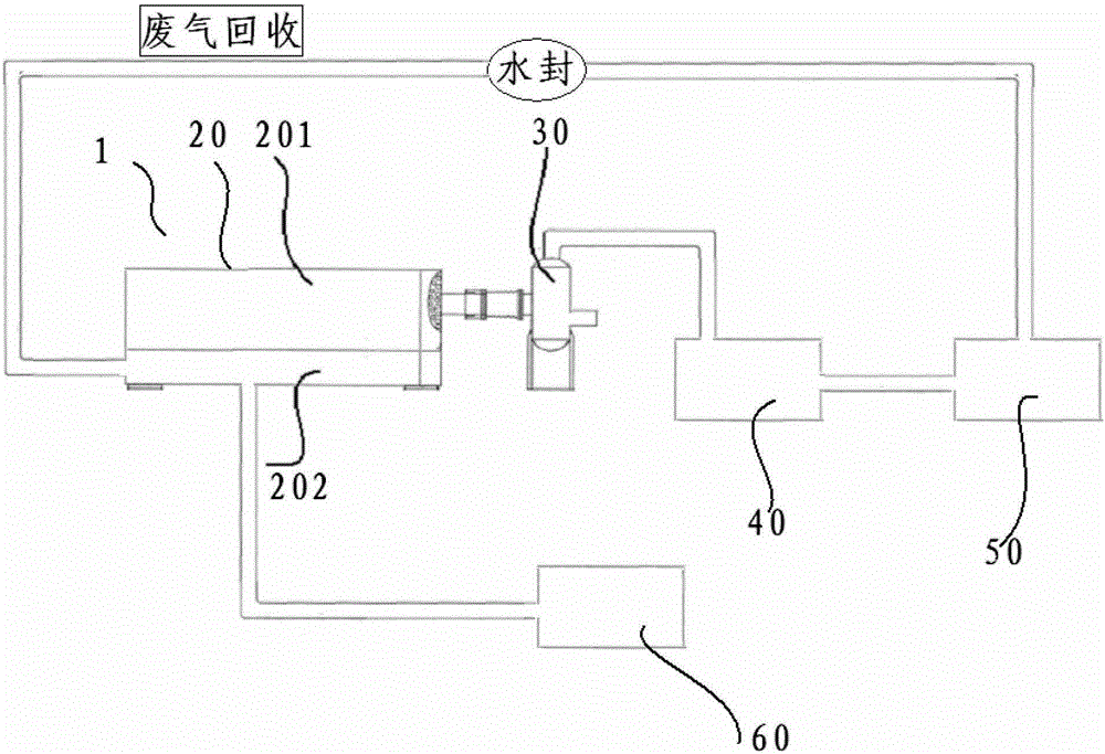
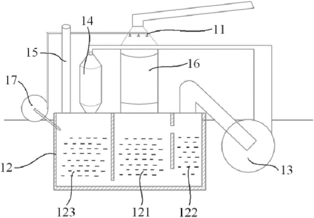
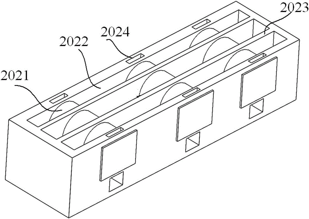
[0028] see Figure 1-4 Said: static cracking equipment 1, comprising: a cracking device 20, a gas separating and filtering device 30 and a cooling device 40 connected in sequence. The cracking device 20 includes a furnace body 201 and a heating device 202 , and the furnace body 201 is arranged on the upper part of the heating device 202 . The heating equipment 202 is composed of a furnace 2021 for placing fuel at intervals and a space 2022 for conducting heat; the furnace body 201 is heated by heat conduction through the heating equipment 202, instead of the steel plate of the furnace body 201 being in direct contact with or contacting, so as to prolong the service life of the equipment. The cooling device 40 includes a water pool 401 , a cooli...


PUM


Abstract

The invention relates to static pyrolysis equipment. The static pyrolysis equipment comprises a pyrolysis device, a gas separating and filtering device and a cooling device which are connected sequentially, wherein the pyrolysis device comprises a furnace body and heating equipment, and the furnace body is arranged at the upper part of the heating equipment; the heating equipment consists of a furnace hearth in which fuel is placed at intervals, and a heat conduction space; the cooling device comprises a water pool and a cooling pipeline; and the cooling pipeline is located inside the water pool and has the diameter of 200-250 mm and the length of 50-80 m. The pyrolysis equipment disclosed by the invention is static and is free of transmission, so that the occurrence of accidents is avoided in the aspect of safety; due to the heating manner and the heat preservation structure, the fuel can be utilized sufficiently, so that the production cost is reduced; and due to the structure of a cooling system, oil vapor is cooled sufficiently during cooling, so that the oil yield is increased, and the benefit is increased directly. The static pyrolysis equipment has the characteristics of power saving, time saving, high yield, long service life, environment friendliness and safety.

Description

technical field [0001] The invention relates to the technical field of water tar cracking equipment, in particular to a static cracking equipment. Background technique [0002] In recent years, energy has been gradually lacking, and environmental pollution has become increasingly serious. All countries in the world have actively established laws and institutions to reduce people's environmental pollution. Among them, the recycling industry has emerged. For example, people recycle waste paper and then process it to produce paper. Waste metals are recovered and then processed and reduced to metals, or waste plastics are recovered and cracked to regenerate oil products. Therefore, the recycling and recycling industry can reduce the pollution of waste to the environment, and the recycled products can also reduce the chance of people continuing to mine and destroy the environment. However, in the regeneration process of waste plastic pyrolysis, a large amount of impurities such a...

Claims


Application Information

Patent Timeline
Patent Type & Authority Patents(China)
IPC IPC(8): C10G1/10B01D50/00
Inventor 唐国圣
Owner HANGZHOU LVHUAN RUBBER & PLASTIC PROD
Learn More