Anti-floating piled raft structure combining deep-layer jet-grouting cement-soil board and anchor and construction method

A technology of cement-soil slab and rotary jetting pile, which is applied in infrastructure engineering, sheet pile wall, protection device, etc., can solve the problems of bolt corrosion, limited contribution of vertical bearing capacity, cracking of grouting body, etc. Vertical bearing capacity, good technical and economic benefits, and the effect of shortening the bolt distance

Inactive Publication Date: 2014-08-20
SHENZHEN GOLDEN CENTURY ENG INDAL
View PDF7 Cites 18 Cited by
  • Summary
  • Abstract
  • Description
  • Claims
  • Application Information

AI Technical Summary

Problems solved by technology

[0005] Although the traditional anti-floating anchor has the above advantages, it also has its shortcomings and shortcomings: firstly, the longer the anchor, the better the anchoring effect of the anchor, but in deep soft soil areas, in order to obtain a good anchoring effect , the length of the anchor is bound to increase, which obviously increases the difficulty and cost of construction; secondly, a longer anchor will inevitably increase the difficulty and quality of grouting, which will affect the anchoring effect; Buried anchors will cause problems such as hole collapse, especially for areas with deep soft soil layers, which will affect the anchoring e...

Method used


Image

  • Anti-floating piled raft structure combining deep-layer jet-grouting cement-soil board and anchor and construction method
  • Anti-floating piled raft structure combining deep-layer jet-grouting cement-soil board and anchor and construction method
  • Anti-floating piled raft structure combining deep-layer jet-grouting cement-soil board and anchor and construction method

Examples


Embodiment Construction

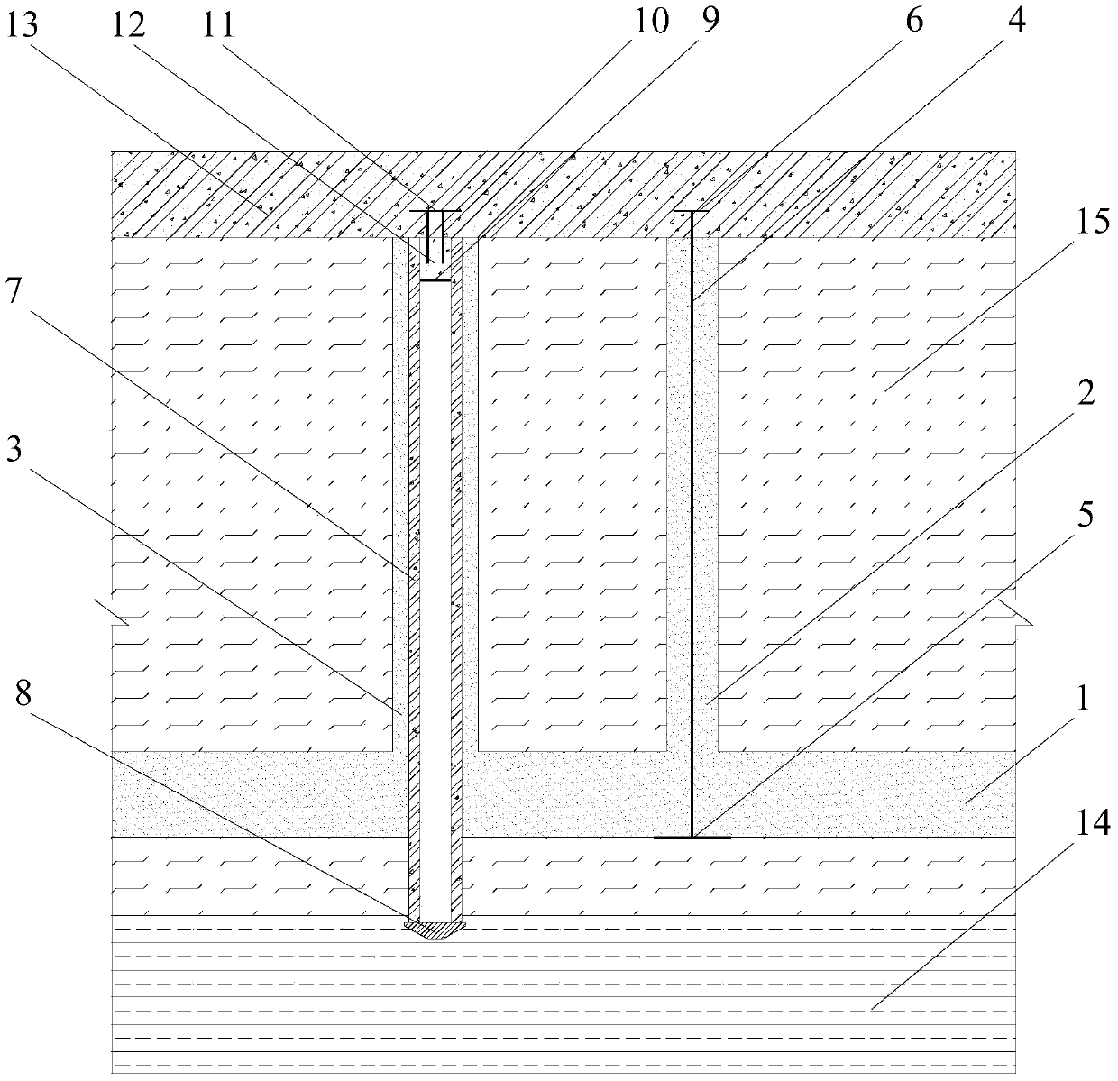
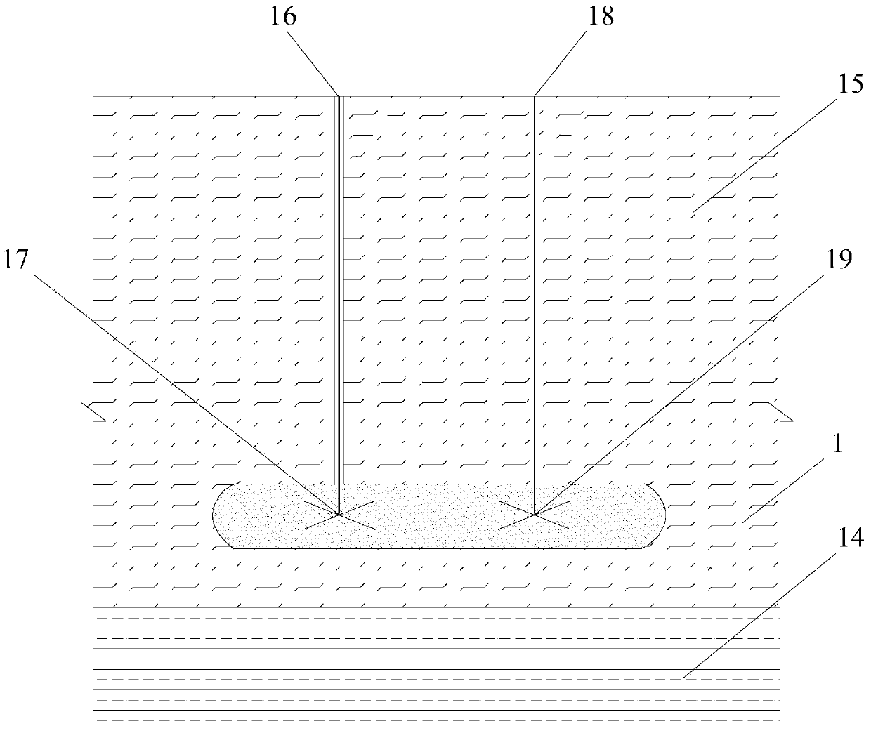
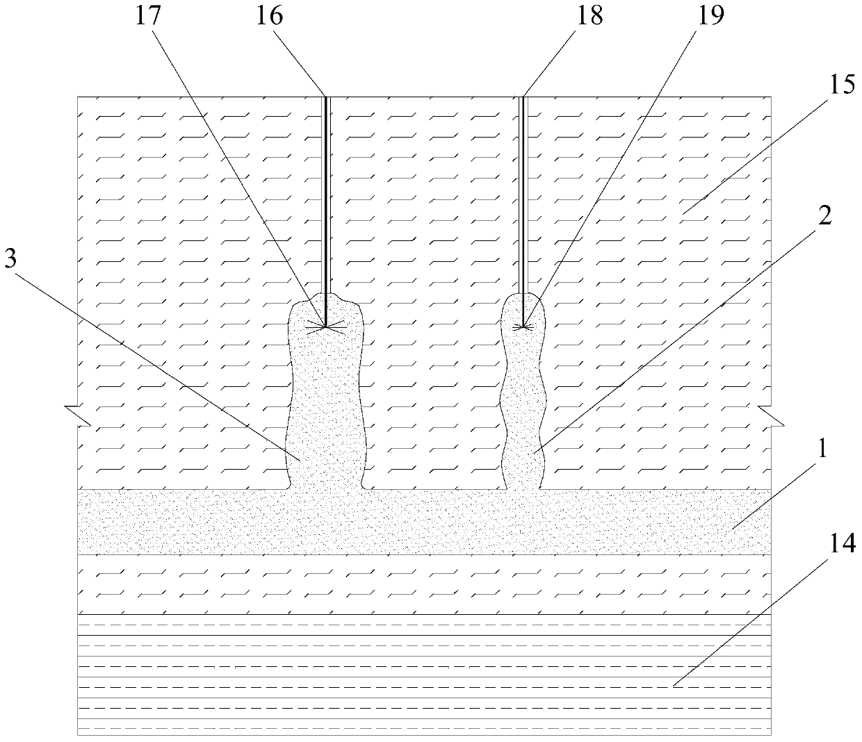
[0038] The present invention will be further described below in conjunction with the accompanying drawings and embodiments. While the invention will be described in conjunction with the preferred embodiments, it will be understood that it is not intended to limit the invention to the described embodiments. On the contrary, the invention is to cover alternatives, modifications and equivalents, which may be included within the scope of the invention as defined by the appended claims.

[0039] In this embodiment, the soft soil drilling design and construction technical requirements, cement-soil mix ratio and construction technical requirements, high-pressure rotary spraying technology and construction technical requirements, steel bar binding, steel plate welding, raft concrete pouring construction technical requirements, this embodiment The description will not be repeated, and the embodiment of the structure related to the present invention will be explained emphatically.

[0...


PUM


Abstract

The invention discloses an anti-floating piled raft structure combining a deep-layer jet-grouting cement-soil board and an anchor and a construction method. A continuous large-thickness deep-layer cement soil board which is formed in a high-pressure jet grouting mode is arranged at the design position in a foundation, a large-diameter jet grouting pile and a small-diameter jet grouting pile are further arranged on the cement soil board, a compound pile of prestressed pipe piles is inserted into the large-diameter jet grouting pile to serve as a vertical bearing pile, the top of the prestressed pipe piles is sealed and provided with an anti-floating screw and an anti-floating end plate, the anti-floating screw and the anti-floating end plate are connected with a raft foundation, the anti-floating anchor is implanted into the small-diameter jet grouting pile, and a rear expansion end plate is arranged at the bottom of the anti-floating anchor, and is arranged at the bottom of the deep-layer cement soil board. The anti-floating piled raft structure combining the deep-layer jet-grouting cement-soil board and the anchor and the construction method have the advantages that the capacity of surrounding soil is fully utilized for resisting buoyancy, a reliable anchoring point is provided for the anchor, the anchor distance can be effectively shortened, and the cost is reduced. Combination of the prestressed pipe piles, the large-diameter high-pressure jet grouting pile, the small-diameter high-pressure jet grouting pile and the short anti-floating anchor is adopted for the foundation, and the good vertical bearing capacity, the high buoyancy resistance performance and the like are achieved.

Description

technical field [0001] The invention relates to a pile raft structure and a construction method, more specifically, it relates to an anti-floating pile raft structure and a construction method of a combination of deep rotary sprayed cement-soil slabs and anchor rods, and belongs to the field of foundation treatment. Background technique [0002] With the rapid development of urban construction, a large number of high-rise buildings, underground garages, sunken squares, subways, underground shopping malls and other buildings have put forward higher requirements for the utilization of underground space. However, in coastal cities such as Shenzhen, Dalian, and Qingdao, where the underground soil is rich in water and the nature of the soil is soft soil with a large thickness, accidents of tilting and collapse of buildings and structures caused by the buoyancy of groundwater occur frequently. , making the basement anti-floating problem increasingly prominent. [0003] Pile-raft ...

Claims


Application Information

Patent Timeline
IPC IPC(8): E02D27/10E02D27/12E02D31/12E02D5/46E02D5/50E02D5/74
Inventor 王新泉
Owner SHENZHEN GOLDEN CENTURY ENG INDAL
Why Eureka
Try Eureka