Desilting, blowing and sand sucking device for construction of bridge foundation steel cofferdam

A bridge foundation, air blowing and sand suction technology, applied in the direction of mechanically driven excavators/dredgers, etc., can solve the problems of poor maneuverability of sand suction ships, weak sand suction ability, underwater mud and sand erosion, etc., and achieve simple structure, Good economy and avoid stuck effect

A bridge foundation, air blowing and sand suction technology, applied in the direction of mechanically driven excavators/dredgers, etc., can solve the problems of poor maneuverability of sand suction ships, weak sand suction ability, underwater mud and sand erosion, etc., and achieve simple structure, Good economy and avoid stuck effect

CN103993619AActive Publication Date: 2014-08-20湖北兴达路桥有限公司 +1

Image

  • Desilting, blowing and sand sucking device for construction of bridge foundation steel cofferdam
  • Desilting, blowing and sand sucking device for construction of bridge foundation steel cofferdam
  • Desilting, blowing and sand sucking device for construction of bridge foundation steel cofferdam

Examples


Embodiment Construction

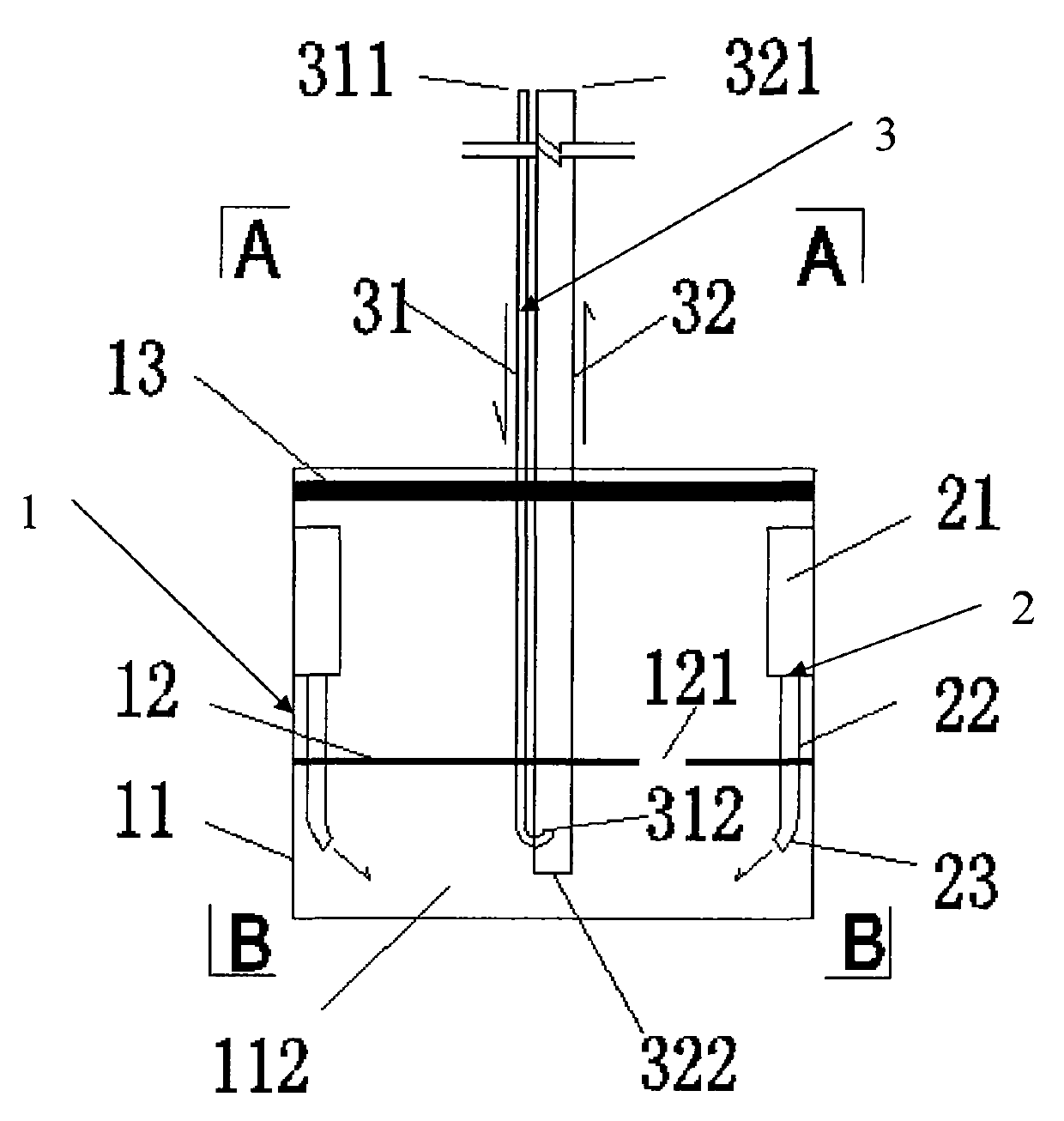
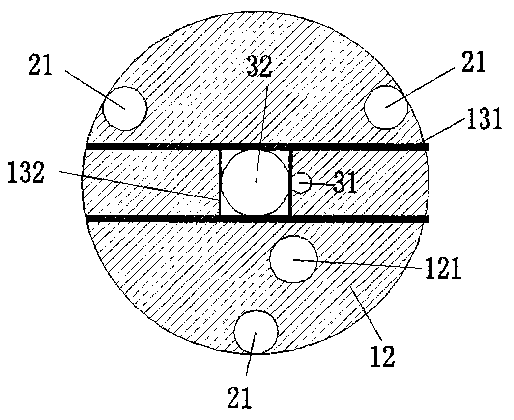
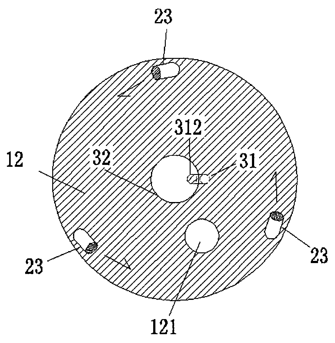
[0022] Such as figure 1 , 2 As shown in . and 3, the air-blowing and sand-absorbing device for bridge foundation steel cofferdam construction includes a cover body 1, a sand-washing device 2 and a sand-absorbing device 3, and the sand-washing device 2 and the sand-absorbing device 3 are arranged in the cover body 1. The sand device 2 gathers the mud and gravel together, and the sand suction device 3 sucks and discharges the mud and gravel to the outside of the cover body (1), wherein:

[0023] The cover body 1 mainly includes a circular steel casing 11, a sealing plate 12, a limit frame 13 and the like. The steel casing 11 is a hollow cylinder made of steel plates, with no cover at the upper and lower ends; the sealing plate 12 is a circular steel plate with the same inner diameter as the steel casing 11, and the sealing plate 12 is vertically fixed at a distance from the steel casing 11. On the inner wall at a certain distance from the bottom end, a closed sand-absorbing sp...


PUM


Abstract

A desilting, blowing and sand sucking device for construction of a bridge foundation steel cofferdam comprises a cover body, a sand flushing device and a sand sucking device, wherein the sand flushing device and the sand sucking device are arranged inside the cover body; the sand flushing device gathers mud gravel; the sand sucking device sucks and discharges the mid gravel out of the cover. The desilting, blowing and sand sucking device for construction of the bridge foundation steel cofferdam has the advantages of being high in efficiency, good in applicability, simple in structure, good in operability, economical efficiency and application prospect, and the like.

Description

technical field [0001] The invention belongs to the field of bridge engineering, and in particular relates to an air-blowing and sand-absorbing device for foundation cleaning of bridge foundation steel cofferdam construction. Background technique [0002] In the construction of underwater bridge piers, steel cofferdams are often used to create a dry working environment. At this time, the bottom of the cofferdam needs to be dredged before the bottom can be sealed. At present, the dredging and sand suction equipment mainly used include sand suction boats and sand suction pumps. [0003] The sand suction ship is suitable for the environment where the ship can pass. Sand suction pumps are often used in places where the water level is shallow. The ability is not strong and the efficiency is low, the aperture is small, it is easy to get stuck, and the energy consumption is high. Therefore need a kind of strong applicability, strong sand suction force, high efficiency, low cost s...

Claims


Application Information

Patent Timeline
20 Aug 2014
Publication
CN103993619A
IPC
E02F3/88
Inventors
罗春风; 何有为