Efficient double-cavity turbulent heat exchanger

A heat exchanger and turbulent flow technology, applied in the field of heat exchange equipment, can solve the problems of high maintenance cost, complex process, low heat exchange efficiency, etc., and achieve the effects of reasonable equipment structure, high heat transfer efficiency, and heat exchange area saving.

Active Publication Date: 2014-08-20
山东鲁润热能科技有限公司
View PDF5 Cites 3 Cited by
  • Summary
  • Abstract
  • Description
  • Claims
  • Application Information

AI Technical Summary

Problems solved by technology

Moreover, the shell-and-tube heat exchanger is prone to fouling, difficult to clean, high maintenance cost, and complicated process
In addition, due to the struc

Method used


Image

  • Efficient double-cavity turbulent heat exchanger
  • Efficient double-cavity turbulent heat exchanger
  • Efficient double-cavity turbulent heat exchanger

Examples


Embodiment 1

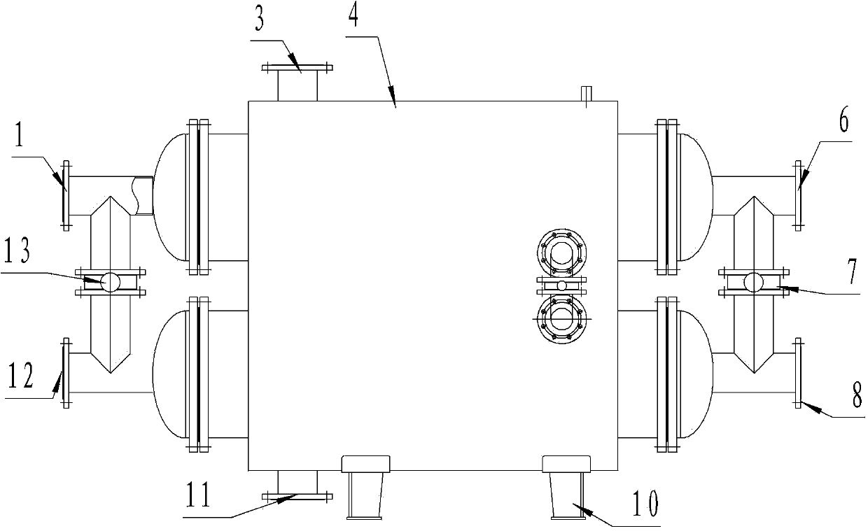
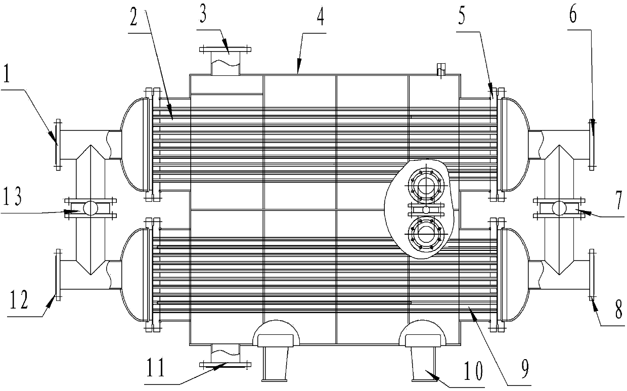
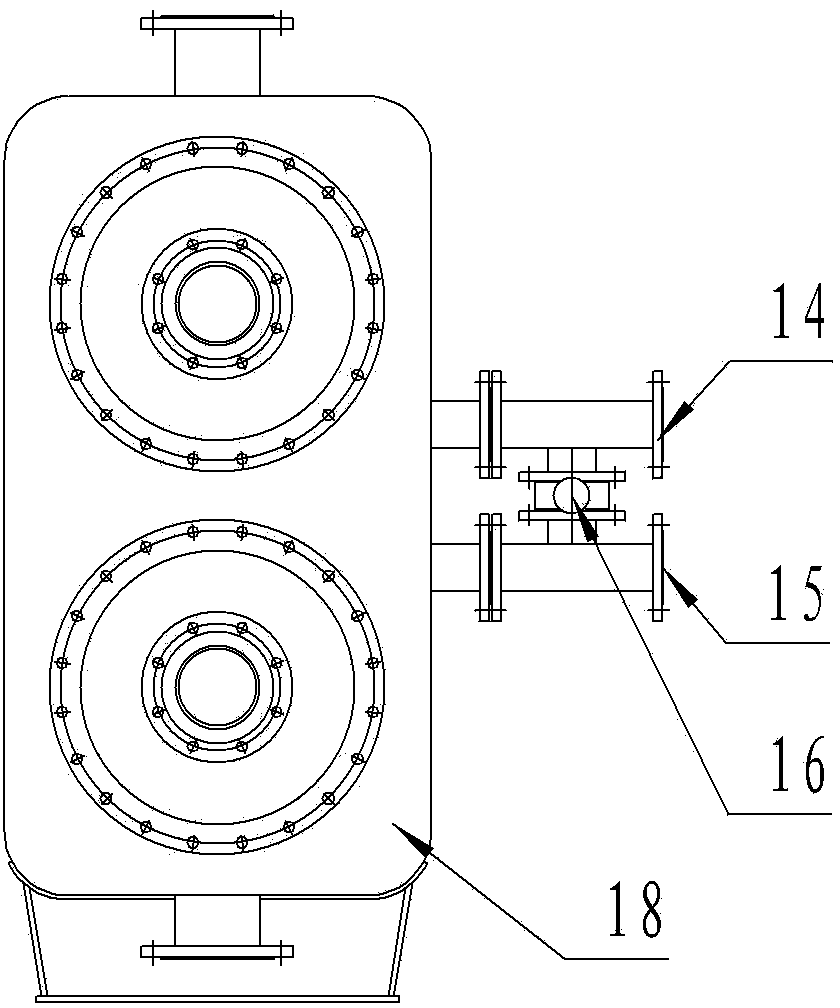
[0021] Embodiment 1, a high-efficiency double-chamber turbulent heat exchanger, including a heat exchanger cylinder 4 equipped with a primary heat medium inlet and a secondary heat medium inlet and outlet, and a heat exchange tube bundle installed in the cylinder. It is characterized in that: The cylinder described above is a rectangular cylinder, and the double-chamber partition 17 in the middle of the rectangular cylinder divides the cylinder into upper and lower chambers. Tube bundle 9, rectangular blocking plates 18 are installed at both ends of the cavity, and circular tube sheets 5 are respectively arranged on the blocking plates. The inlet and outlet of the secondary heat medium are respectively set on the upper and lower chambers at the same end, and a connection switch is provided between the inlet and outlet of the secondary heat medium of the upper and lower chambers at the same end, that is, the secondary double-cavity connection switch 13 at the front end and the s...


PUM


Abstract

The invention discloses an efficient double-cavity turbulent heat exchanger, belongs to a heat exchange device, and particularly relates to a heat exchange device in which two heat mediums do not make direct contact. The heat exchanger comprises a heat exchanger barrel body with a primary heat medium inlet, a primary heat medium outlet, a secondary heat medium inlet and a secondary heat medium outlet, and heat exchange tube bundles installed in the barrel body. The heat exchanger is characterized in that the barrel body is rectangular, a double-cavity partition plate in the middle of the rectangular barrel body divides the barrel body into an upper cavity and a lower cavity, the interior of the upper cavity and the interior of the lower cavity are respectively provided with one heat exchange tube bundle, the two ends of each cavity are respectively provided with a rectangular blocking plate, a round tube plate is arranged on each blocking plate, the two ends of each turbulent thread heat exchange tube are fixed to the tube plates, the outer sides of the tube plates are connected with a tube box through bolts, the secondary heat medium inlet and the secondary heat medium outlet are respectively formed in the tube box, a coupling cock is arranged between the secondary heat medium inlet and the secondary heat medium outlet of the upper cavity and the lower cavity located at the same end, the primary heat medium inlet and the primary heat medium outlet are formed in the upper portion and the lower portion of the barrel body respectively, a primary heat medium standby inlet and a primary heat medium standby outlet are formed in the portions, on the two sides of the double-cavity partition plate, of the barrel body respectively, and a primary heat medium double-cavity coupling cock is installed between the primary heat medium standby inlet and the primary heat medium standby outlet.

Description

technical field [0001] The invention belongs to heat exchange equipment, in particular to heat exchange equipment in which two heat mediums do not directly contact each other. Background technique [0002] With the rapid development of modern industry, energy-centered environmental and ecological issues are becoming more and more serious. While the country is looking for new energy sources, it has also paid more attention to the research and development of new energy-saving methods. The application of enhanced heat transfer technology can not only save energy, protect the environment, but also greatly save investment costs. Shell-and-tube heat exchangers are also called shell-and-tube heat exchangers. At present, in industrial production at home and abroad, shell-and-tube heat exchangers still dominate in heating and heating, but the shortcomings of shell-and-tube heat exchangers in their application Also very obvious. Shell-and-tube heat exchangers are heavy and bulky, an...

Claims


Application Information

Patent Timeline
IPC IPC(8): F28D7/00F28F1/10F28F9/00F28F9/10F28F9/24F28F27/00
Inventor 房玉刚董林峰
Owner 山东鲁润热能科技有限公司
Why Eureka
Try Eureka