Sound wave receiving transducer and underground azimuth noise leak detecting device and method
An acoustic wave receiving and transducer technology, applied in seismic signal receivers, measuring devices, instruments, etc., can solve the problems of lack of directivity, faults and other geological structures, and the accuracy of experimental data cannot be guaranteed.
- Summary
- Abstract
- Description
- Claims
- Application Information
AI Technical Summary
Problems solved by technology
Method used
Image

Examples
Embodiment Construction
[0020] The present invention will be described in detail below in conjunction with the accompanying drawings.
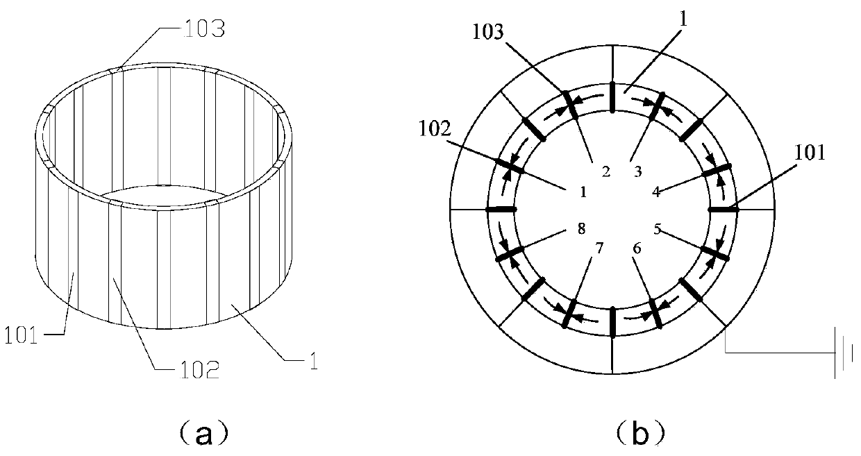
[0021] Such as figure 1 As shown, a sound wave receiving transducer, the transducer is composed of a piezoelectric ceramic cylinder and a plurality of silver electrode rectangular strips covering the inner and outer walls of the piezoelectric ceramic cylinder along the circumferential direction, each silver electrode Covering the inner and outer walls of the piezoelectric ceramic cylinder at equal intervals, the corresponding silver electrodes on the inner and outer walls of the piezoelectric ceramic cylinder are connected together through the silver bridge 103 covering the top or bottom edge of the piezoelectric ceramic cylinder, The polarization direction of the piezoelectric ceramic between each silver electrode is parallel to the tangential direction of the piezoelectric ceramic cylinder, and the piezoelectric ceramic between each silver electrode is polarized to...
PUM
 Abstract
Description
Claims
Application Information