Optical transceiver module

A technology of optical transceiver module and optical transmitter, which is applied in the field of optical communication, can solve problems such as easy detachment of optical fibers, lower installation accuracy of optical fibers, and poor coupling effect of optical transceiver modules, so as to achieve high reliability of optical paths, improve coupling effects, and good effect

Active Publication Date: 2014-08-20
旭创科技有限公司
View PDF9 Cites 2 Cited by
  • Summary
  • Abstract
  • Description
  • Claims
  • Application Information

AI Technical Summary

Problems solved by technology

[0005] In the above structure, since a V-shaped groove is provided on the substrate, it is difficult for the V-shaped groove to accurately match the outer diameter of the optical fiber, and the optical fiber is easy to fall off the V-shaped groove during the fixing process, so it is difficult to accurately control the fixed position of the optical fiber. , which reduces the installation accuracy of the optical fiber, resulting in poor coupling effect of the optical transceiver module

Method used


Image

  • Optical transceiver module
  • Optical transceiver module
  • Optical transceiver module

Examples


Embodiment Construction

[0042] The present invention will be described in detail below in conjunction with specific embodiments shown in the accompanying drawings. However, these embodiments do not limit the present invention, and any structural, method, or functional changes made by those skilled in the art according to these embodiments are included in the protection scope of the present invention.

[0043] For the convenience of description, the operator's observation angle is used as the reference direction for detailed description, and up, down, left, and right appearing below are all reference angles.

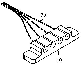
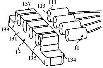
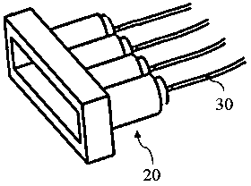
[0044] The optical transceiver module includes a housing, a circuit board disposed in the housing, a light emitting component and / or a light receiving component (not shown in detail), the light transmitting component includes a light transmitter and an optical interface, and the light receiving component includes The optical receiver and the optical input interface, the optical transmitter and t...


PUM


Abstract

The invention provides an optical transceiver module which comprises optical fiber and an optical fiber locating structure fixing the optical fiber. The optical fiber locating structure comprises a first locating part fixing the optical fiber, and a first supporting part fixing the first locating part to a shell. The first locating part comprises a first end face, a second end face and a first through hole, wherein the first end face and the second end face are arranged oppositely, and the through hole is used for being communicated with the first end face and the second end face. The aperture of the first through hole is equal to the diameter of the optical fiber. The optical fiber is fixed into the first through hole. The first supporting part is provided with a containing part containing the first locating part. The first locating part is fixed to the containing part. Compared with the prior art, the optical transceiver module comprises the optical fiber locating structure which is more reasonable, and the optical fiber can be located more accurately in the optical transceiver module; furthermore, the stability of transmission of the light path in the optical transceiver module with the optical fiber locating structure is improved.

Description

technical field [0001] The invention relates to the field of optical communication, in particular to an optical transceiver module. Background technique [0002] With the development of science and technology, high-speed transmission signal technology is widely used, optical interconnection can transmit signals over a much wider bandwidth than electrical transmission, and use small-sized, low-power optical transceiver modules to construct signal transmission systems. Therefore, high-speed signal transmission technology has turned its attention to optical interconnection as a signal transmission technology between devices. Correspondingly, optical transceiver modules installed in computers, vehicles, etc. as electronic components are widely used. [0003] During the use of the optical transceiver module, it is necessary to couple its internal optical fiber with a chip, lens, etc. at its transmitting end and / or receiving end. Correspondingly, in order to achieve a better cou...

Claims


Application Information

Patent Timeline
IPC IPC(8): G02B6/42
CPCG02B6/3644G02B6/4292G02B6/4243
Inventor 杜寅超王帅杰李伟龙施高鸿
Owner 旭创科技有限公司
Why Eureka
Try Eureka