

Method for making optical fiber spherical-surface micro lens in three steps of corrosion, cutting and hot melting
A technology of microlens and optical fiber, which is applied in the coupling of optical waveguide, light guide, optics, etc. It can solve the problems of large size error, influence on coupling effect, uncontrollable curvature radius of optical fiber spherical microlens, etc., and achieve accurate size and good coupling effect Effect
- Summary
- Abstract
- Description
- Claims
- Application Information
AI Technical Summary
Problems solved by technology
Method used
Image

Examples
Embodiment Construction
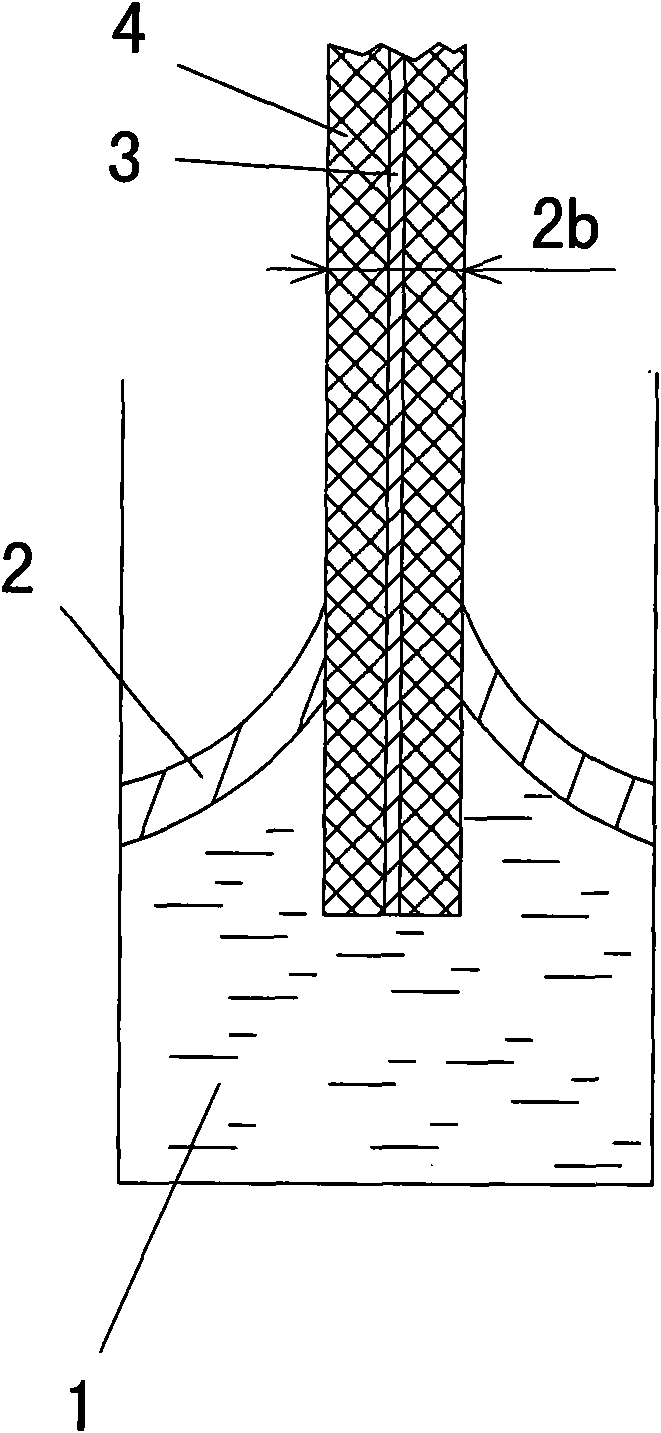
[0019] Such as figure 1 , 2 , 3, 4, and 5: 1 is HF acid solution, and the optical fiber is composed of an inner core 3 and a cladding 4 wrapped outside.
[0020] The steps of the present invention are:
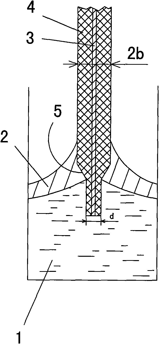
[0021] ① Corrosion, using HF acid solution 1 to corrode the end of the optical fiber to make the outer diameter 2d of the end of the optical fiber smaller and form a transition shape with the uncorroded part through the tapered surface 5 . There is an organic covering layer 2 above the HF acid solution 1, and the organic covering layer 2 is an organic covering layer of xylene or other materials.
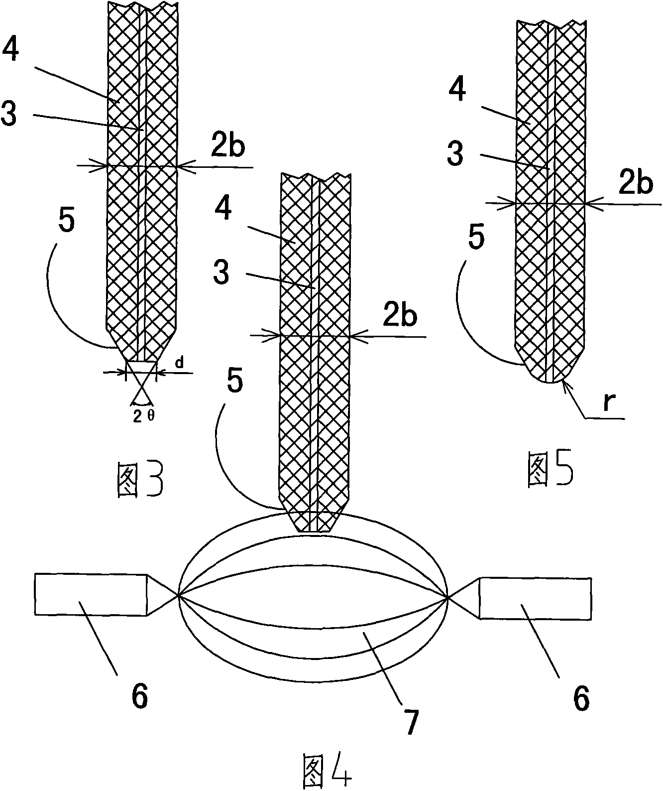
[0022] ②. Cut the flat end face, and cut off the small diameter d part formed at the end of the optical fiber. After cutting, the end of the optical fiber is in the shape of a perfect circular table;
[0023] ③, using the temperature field 7 generated by the electrode 6 to heat-melt the fiber end to form a spherical optical fiber micro-lens, and the radius of curvature of the sphe...
PUM
 Abstract
Description
Claims
Application Information