
A phase change cooling device and its manufacturing method

A technology of a heat dissipation device and a manufacturing method, applied in the direction of cooling/ventilation/heating transformation, etc., can solve the problems that the heat dissipation method is difficult to function, cannot meet the working requirements of the equipment, and the heat capacity is small, so as to achieve a clear manufacturing process and strong designability. , the effect of large heat capacity

Active Publication Date: 2017-05-17
SOUTHWEST CHINA RES INST OF ELECTRONICS EQUIP
View PDF4 Cites 0 Cited by
  • Summary
  • Abstract
  • Description
  • Claims
  • Application Information

AI Technical Summary

Problems solved by technology

[0002] The heat dissipation of traditional electronic equipment dissipates heat outside the system through convection, conduction and radiation. However, for some electronic equipment in confined spaces, traditional heat dissipation methods are difficult to play a role, and often only through the metal heat of the equipment structure itself. sink to absorb heat from electronics
This heat dissipation method has a small heat capacity and cannot meet the working requirements of most equipment

Method used


Image

  • A phase change cooling device and its manufacturing method
  • A phase change cooling device and its manufacturing method
  • A phase change cooling device and its manufacturing method

Examples


Embodiment 1

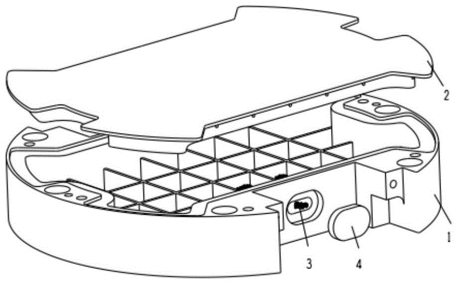
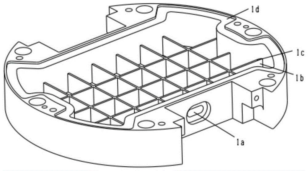
[0033] The phase change heat dissipation device designed in this embodiment is composed of a base body, a cover plate, a phase change material and an encapsulation block. The base body is a shell with slots on one side. The size of the base body of the phase change heat dissipation device is 154mm (length) × 204mm (width) × 25mm (height). In the region, the thickness of the thermally conductive ribs is 1mm, the spacing is 11mm, and the height is 15mm, and the height of the thermally conductive ribs is lower than that of the periphery of the substrate. The heat conduction reinforcing rib can not only improve the heat conduction performance between the base body and the cover plate, but also enhance the expansion and bending resistance mechanical properties of the shell.

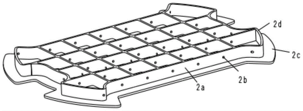
[0034] The cover plate is a flat plate with reinforcing ribs on one side, the thickness of the cover plate is 1.5mm, the thickness of the reinforcing ribs on it is 1mm, the height is 7mm, and the spacing is 11...

Embodiment 2

[0051] The phase change heat dissipation device designed in this embodiment is composed of a base body, a cover plate, a phase change material and an encapsulation block. The base body is a shell with grooves on one side. The size of the base body of the phase change heat sink is φ120mm×20mm (height). The groove is provided with thermally conductive reinforcing ribs, which divide the inside of the shell into multiple sub-regions, wherein the thickness of the thermally conductive reinforcing ribs is 1.5mm, the spacing is 15mm, the height is 13mm, and the height of the heat conduction rib is lower than the peripheral height of the base. The heat conduction reinforcing rib can not only improve the heat conduction performance between the base body and the cover plate, but also enhance the expansion and bending resistance mechanical properties of the shell.

[0052]The cover plate is a flat plate with reinforcing ribs on one side, the thickness of the cover plate is 1.5mm, the thic...


PUM


Abstract

The invention provides a phase change heat dissipation device and a manufacturing method thereof. The phase change heat dissipation device is composed of a base body, a cover plate, a phase change material and a packaging block. The base body is a case with one surface provided with a groove, and heat conduction reinforcement ribs are arranged in the groove and divide the interior of the case into a plurality of sub-areas. An opening is formed in the side surface of the base body and used for phase change material pouring. The cover plate is a flat plate with one surface provided with reinforcement ribs, the reinforcement ribs of the cover plate are provided with communication holes in all directions, and all sub-areas formed by the reinforcement ribs of the cover plate are communicated through the communication holes. The packaging block and the opening in the side surface of the base body are in interference fit. The thermal capacity of the phase change heat dissipation device is large and is more than twice that of a traditional metal heat sink so that the heating rate of electronic equipment can be greatly reduced. Meanwhile, the reliability of the phase change heat dissipation device is high. Compared with the traditional air cooling or liquid cooling heat dissipation technology, the number of moving parts is reduced, influence on the electronic equipment from impact vibration is eliminated, and the failure rate of the heat dissipation device is lowered.

Description

technical field [0001] The invention relates to the technical field of heat dissipation of electronic equipment, in particular to a phase change heat dissipation device and a manufacturing method thereof. Background technique [0002] Traditional electronic equipment dissipates heat out of the system through convection, conduction and radiation. However, for some electronic equipment in confined spaces, traditional heat dissipation methods are difficult to play a role, and often only through the metal heat of the equipment structure itself. sink to absorb heat from the electronics. This heat dissipation method has a small heat capacity and cannot meet the working requirements of most equipment. Contents of the invention [0003] technical problem to be solved [0004] In order to solve the problems existing in the prior art, the present invention proposes a phase change heat dissipation device and a manufacturing method thereof. [0005] Technical solutions [0006] Ph...

Claims


Application Information

Patent Timeline
Patent Type & Authority Patents(China)
IPC IPC(8): H05K7/20
Inventor 刘芬芬尹本浩彭勃
Owner SOUTHWEST CHINA RES INST OF ELECTRONICS EQUIP
Learn More