CO2 laser device and CO2 laser processing device

一种激光装置、激光加工的技术,应用在激光器、激光焊接设备、激光器零部件等方向,达到光束直径稳定、高输出的效果

Active Publication Date: 2014-08-20
MITSUBISHI ELECTRIC CORP
View PDF6 Cites 1 Cited by
  • Summary
  • Abstract
  • Description
  • Claims
  • Application Information

AI Technical Summary

Problems solved by technology

[0003] CO described in Patent Document 1 2 The laser device has: a housing which will contain the CO 2 The gas gain medium is accommodated inside; the laser resonator, which includes a high reflector and an output coupler; the excitation device, which excites the gain medium; and the acousto-optic (AO) unit, which is configured in the laser resonator, the CO 2 The laser device uses an AO unit to switch the laser resonator between a high-loss state and a low-loss state, generating Q-switched pulses, but the laser output is limited to less than or equal to the light-resistant power of the acousto-optic unit (for example, several hundred W)

Method used


Image

  • CO2 laser device and CO2 laser processing device
  • CO2 laser device and CO2 laser processing device
  • CO2 laser device and CO2 laser processing device

Examples


Embodiment approach 1

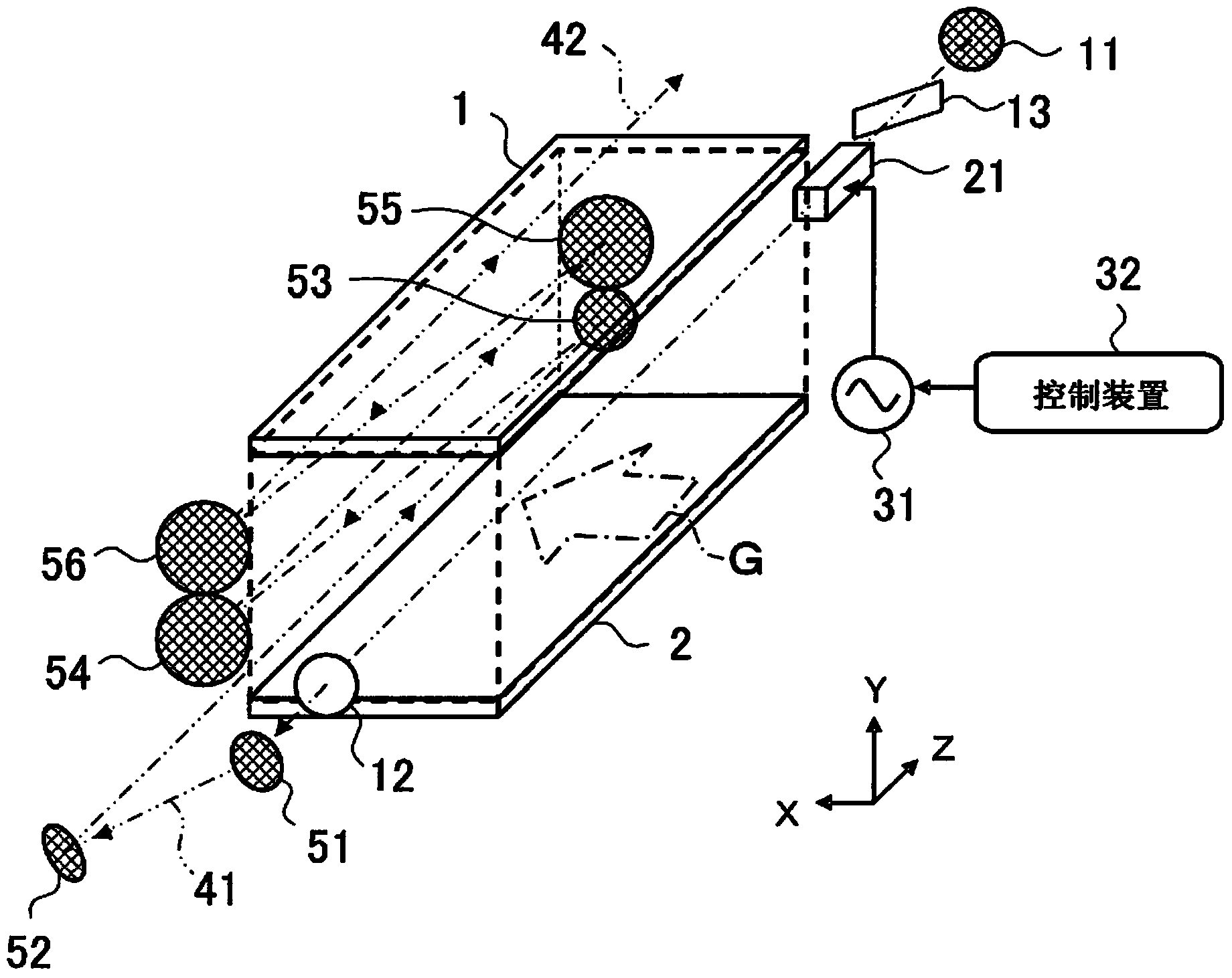
[0020] figure 1 is a transparent representation of CO according to Embodiment 1 of the present invention 2 Oblique view of the structure of the laser device.

[0021] exist figure 1 Medium, CO 2 The laser device has: electrodes 1 and 2, which are arranged up and down; laser gas G (the gas flow direction on the electrode 2 side is indicated by a single-dot dash arrow), which is enclosed in the discharge space between electrode 1 and electrode 2; total reflection mirror 11, which serves as a resonator mirror; a partial mirror 12, which is arranged opposite to the total reflection mirror 11 with the laser gas G interposed therebetween, and serves as a resonator mirror; and a Brewster plate 13, which imparts linear polarization to laser light the acousto-optic element 21, which becomes a modulation element (optical switch) for light modulation; the power supply 31, which applies an AC voltage to the acousto-optic element 21; and the control device 32, which controls the power s...

Embodiment approach 2

[0133] In addition, in the above-mentioned Embodiment 1 ( figure 1 ), the total reflection mirror 11 and the partial reflection mirror 12 are relatively arranged on a straight line through the laser gas G, and there is a Brewster plate 13 that imparts linear polarization to the laser light between them, but as Figure 7 As shown, on one side of the laser gas G, the total reflection mirror 11, the acousto-optic element 21 and the partial reflection mirror 12 can be arranged side by side, and on the opposite side across the laser gas G, the reflection mirror 14, which turns the light back, is set. 15.

[0134] Figure 7 is a transparent representation of the CO related to Embodiment 2 of the present invention 2 Oblique view of the laser processing device, for the aforementioned ( figure 1 ), the same structure as above is marked with the same reference numerals and detailed description is omitted.

[0135] exist Figure 7 CO shown 2 In the laser processing device, replace ...

Embodiment approach 3

[0151] In addition, in the above-mentioned Embodiments 1 and 2 ( Figure 1 to Figure 7 ), for CO that emits a high output and stable laser 42 2 Laser devices are described, but as Figure 8 As shown, it is also possible to constitute a CO 2 Laser processing device.

[0152] Figure 8 is a transparent representation of CO according to Embodiment 3 of the present invention 2 The oblique view of the laser processing device, for the aforementioned (refer to figure 1 ), the same structure as above is marked with the same reference numerals and detailed description is omitted.

[0153] exist Figure 8 In, CO 2 Laser processing device in the aforementioned ( figure 1 ) CO 2 On the basis of the laser device, there are: a transmission optical system 61, which is composed of optical system elements (mirrors, lenses, etc.); an aperture (aperture) 62, which allows the laser light 42 to pass through and enter the transmission optical system 61; A mirror 71 scans the laser beam 43...


PUM

PropertyMeasurementUnit
wavelengthaaaaaaaaaa
frequencyaaaaaaaaaa
poweraaaaaaaaaa

Abstract

The purpose of the present invention is to obtain a CO2 laser device and CO2 laser processing device for beaming at high output a pulse laser having a stable beam diameter that is not dependent on the repeat frequency. The present invention is provided with: laser gas (G), which acts as a CO2 laser medium; a nearly concentric stable optical resonator installed so that the curvature radius of at least one resonator mirror is equal to the distance between the optical switch and the resonator mirror; an optical switch provided within the stable optical resonator; and transmission mirrors (51-56) provided so that the laser light (41) generated from the stable optical resonator passes through the CO2 laser medium again.

Description

technical field [0001] The present invention relates to a CO 2 Laser device and CO 2 A laser processing device that generates CO from a laser oscillator (optical resonator incorporating a gain medium) 2 Laser (hereinafter referred to as "Laser"). Background technique [0002] Currently, a CO 2 A laser that generates laser light from an optical resonator including a gain medium (for example, refer to Patent Document 1). [0003] CO described in Patent Document 1 2 The laser device has: a housing which will contain the CO 2 The gas gain medium is accommodated inside; the laser resonator, which includes a high reflector and an output coupler; the excitation device, which excites the gain medium; and the acousto-optic (AO) unit, which is configured in the laser resonator, the CO 2 Laser devices use an AO unit to switch the laser resonator between a high-loss state and a low-loss state, generating Q-switched pulses, but the laser output is limited to less than or equal to t...

Claims


Application Information

Patent Timeline
Patent Type & Authority Applications(China)
IPC IPC(8): H01S3/08B23K26/064G02F1/11H01S3/097H01S3/115H01S3/117
CPCH01S3/2366B23K26/0626B23K26/06H01S3/036H01S3/2232H01S3/08G02F1/11H01S3/08054H01S3/117H01S3/0971B23K26/0639H01S3/2325B23K26/0656H01S3/076H01S3/097H01S3/0816H01S3/115B23K26/064B23K26/066
Inventor 谷野阳一西前顺一
Owner MITSUBISHI ELECTRIC CORP
Why Eureka
Try Eureka