
Crystal pulling method and crystal pulling device

A control device and crystal ingot technology, applied in chemical instruments and methods, self-melt pulling method, single crystal growth, etc., can solve the problems of periodic changes in diameter, difficulty in controlling crystal ingot diameter, and convective behavior of silicon solution Complicated problems, to achieve the effect of stable crystal rod diameter and reduce the fluctuation of solid-liquid interface temperature

Inactive Publication Date: 2021-05-25
ZING SEMICON CORP
View PDF5 Cites 1 Cited by
  • Summary
  • Abstract
  • Description
  • Claims
  • Application Information

AI Technical Summary

Problems solved by technology

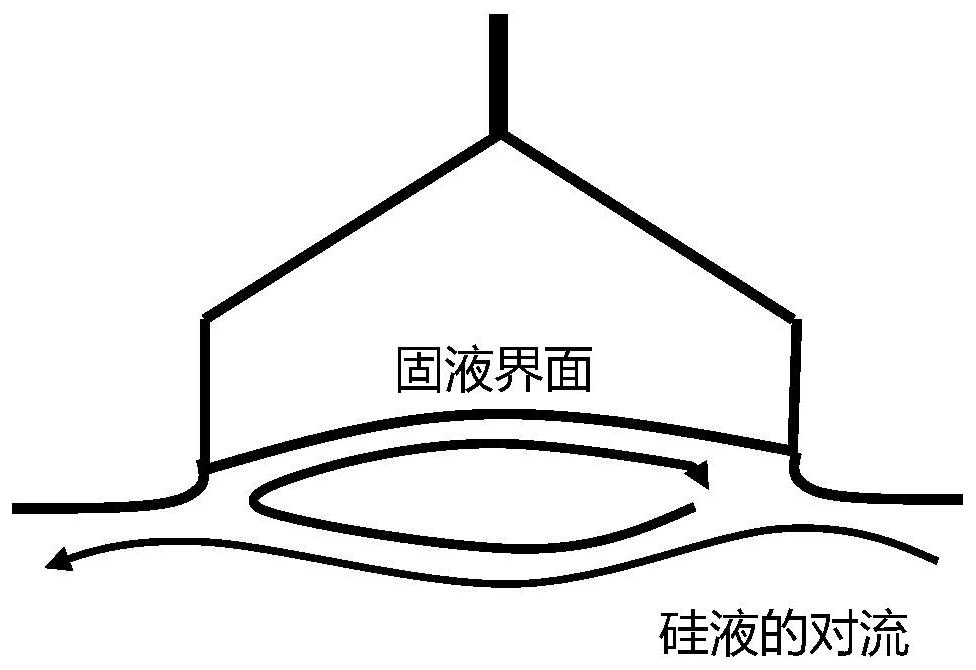
In this process, due to the change of the magnetic field changes the convection velocity of the silicon melt, coupled with the rotation of the quartz crucible and the crystal rod itself, the convection behavior of the silicon solution in the crucible becomes quite complicated.
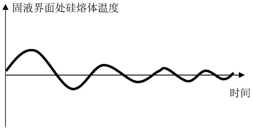
Usually, within a period of time after changing the magnetic field strength, the diameter control of the ingot becomes relatively difficult, and the diameter is prone to periodic changes

Method used


Image

  • Crystal pulling method and crystal pulling device
  • Crystal pulling method and crystal pulling device
  • Crystal pulling method and crystal pulling device

Examples


Embodiment 1

[0041] In order to solve the problems in the prior art, the invention provides a crystal pulling method, comprising:

[0042] During the crystal pulling process, the crucible for containing the silicon melt is kept rotating while applying a horizontal magnetic field to the silicon melt in the crucible, wherein,

[0043] When and / or after changing the magnetic field strength of the magnetic field, the rotation speed of the crucible is changed.

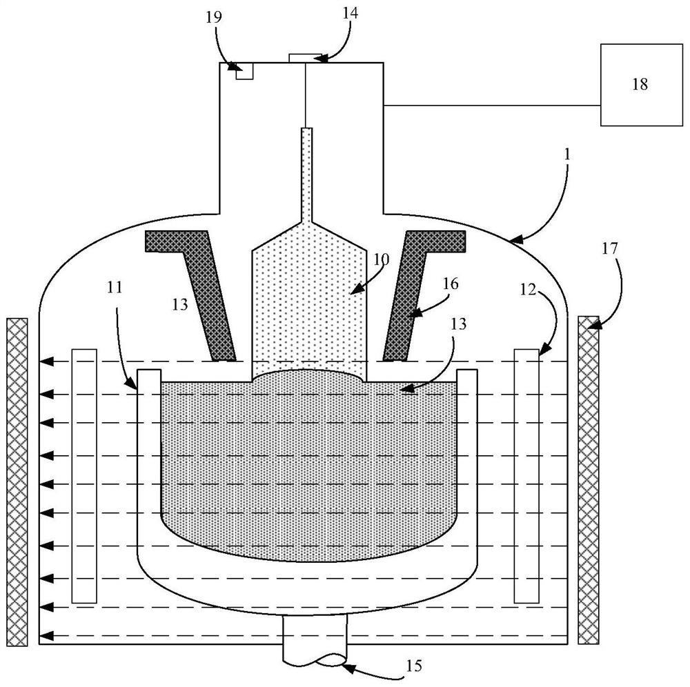
[0044] see figure 1 , shows a schematic structural view of a crystal pulling device according to the present invention, the crystal pulling device includes a furnace body 1, a crucible 11 is arranged in the furnace body 1, a heater 12 for heating it is arranged outside the crucible 11, and the crucible 11 A silicon melt 13 is contained therein.

[0045] Exemplarily, the crucible 11 is composed of a graphite crucible and a quartz crucible sleeved in the graphite crucible. The graphite crucible is heated by a heater to melt the polysili...

Embodiment 2

[0078] The present invention also provides a crystal pulling device, which includes:

[0079] a crucible to contain the silicon melt;

[0080] a pulling device for pulling the silicon melt to form crystal rods;

[0081] a magnetic field applying device, used to apply a horizontal magnetic field to the silicon melt in the crucible and adjust the magnetic field strength of the magnetic field;

[0082] a driving device for driving the crucible to rotate, wherein,

[0083] In the crystal pulling device according to the present invention, a control device is further included, and the control device controls the adjustment of the rotation speed of the crucible by the driving device according to the magnetic field strength of the magnetic field applied by the magnetic field applying device. Specifically, the method for the control device to control the adjustment of the rotation speed of the crucible by the driving device according to the magnetic field strength of the magnetic fie...


PUM


Abstract

The invention discloses a crystal pulling method and a crystal pulling device. The method comprises the steps that in the crystal pulling process, a crucible used for containing a silicon melt is kept rotating, meanwhile, a magnetic field in the horizontal direction is applied to the silicon melt in the crucible, wherein when the magnetic field intensity of the magnetic field is changed and / or after the magnetic field intensity of the magnetic field is changed, fluctuation of the solid-liquid interface temperature of a silicon crystal bar and the melt is likely to be caused; the forced convection of the silicon melt in the crucible is changed by changing the rotating speed of the crucible, so that the temperature fluctuation of a solid-liquid interface caused by the change of the magnetic field intensity is quickly reduced, and the diameter of a crystal bar obtained in the crystal pulling process tends to be stable.

Description

technical field [0001] The invention relates to the technical field of semiconductors, in particular to a crystal pulling method and a crystal pulling device. Background technique [0002] The Czochralski method (Cz) is an important method for preparing silicon single crystals for semiconductors and solar energy. The high-purity silicon material placed in the crucible is heated to melt it through a thermal field composed of carbon materials, and then the seed crystal is immersed in the The melt goes through a series of processes (material melting, temperature stabilization, seeding, shouldering, equal diameter, finishing, cooling) to finally obtain a single crystal ingot. [0003] In the crystal rod growth of semiconductor single crystal silicon or solar single crystal silicon using the CZ method, the temperature distribution of the crystal rod and the melt directly affects the quality and growth rate of the crystal rod. During the growth of CZ ingot, due to the thermal con...

Claims


Application Information

Patent Timeline
Patent Type & Authority Applications(China)
IPC IPC(8): C30B29/06C30B30/04C30B15/22
CPCC30B29/06C30B30/04C30B15/22C30B15/305C30B15/10C30B15/14C30B15/206C30B15/30
Inventor 沈伟民雷友述
Owner ZING SEMICON CORP
Learn More