Resistance spot welding device

Active Publication Date: 2018-02-15
JFE STEEL CORP
View PDF3 Cites 1 Cited by
  • Summary
  • Abstract
  • Description
  • Claims
  • Application Information

AI Technical Summary

Benefits of technology

[0040]According to embodiments of the present invention, when a sheet set including at least two overlapping steel shee

Problems solved by technology

However, the methods described in Patent Literatures 1 to 4 still have a problem in that it is difficult to ensure a nugget diameter stably.
In particular, at a welding site for actual automobile assembly, unintended work distur

Method used


Image

  • Resistance spot welding device
  • Resistance spot welding device
  • Resistance spot welding device

Examples


example 1

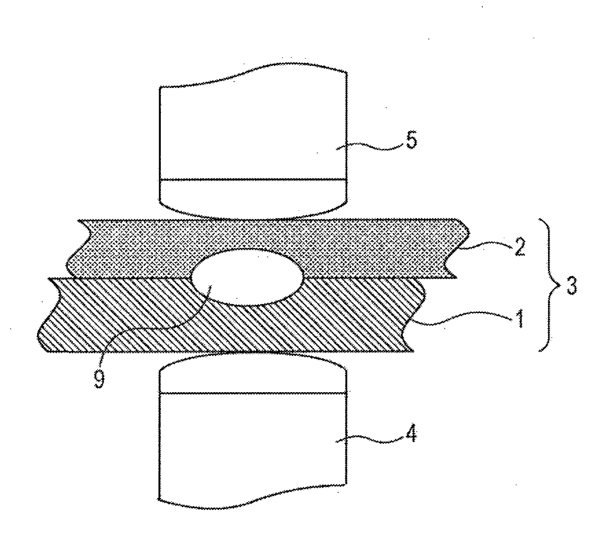
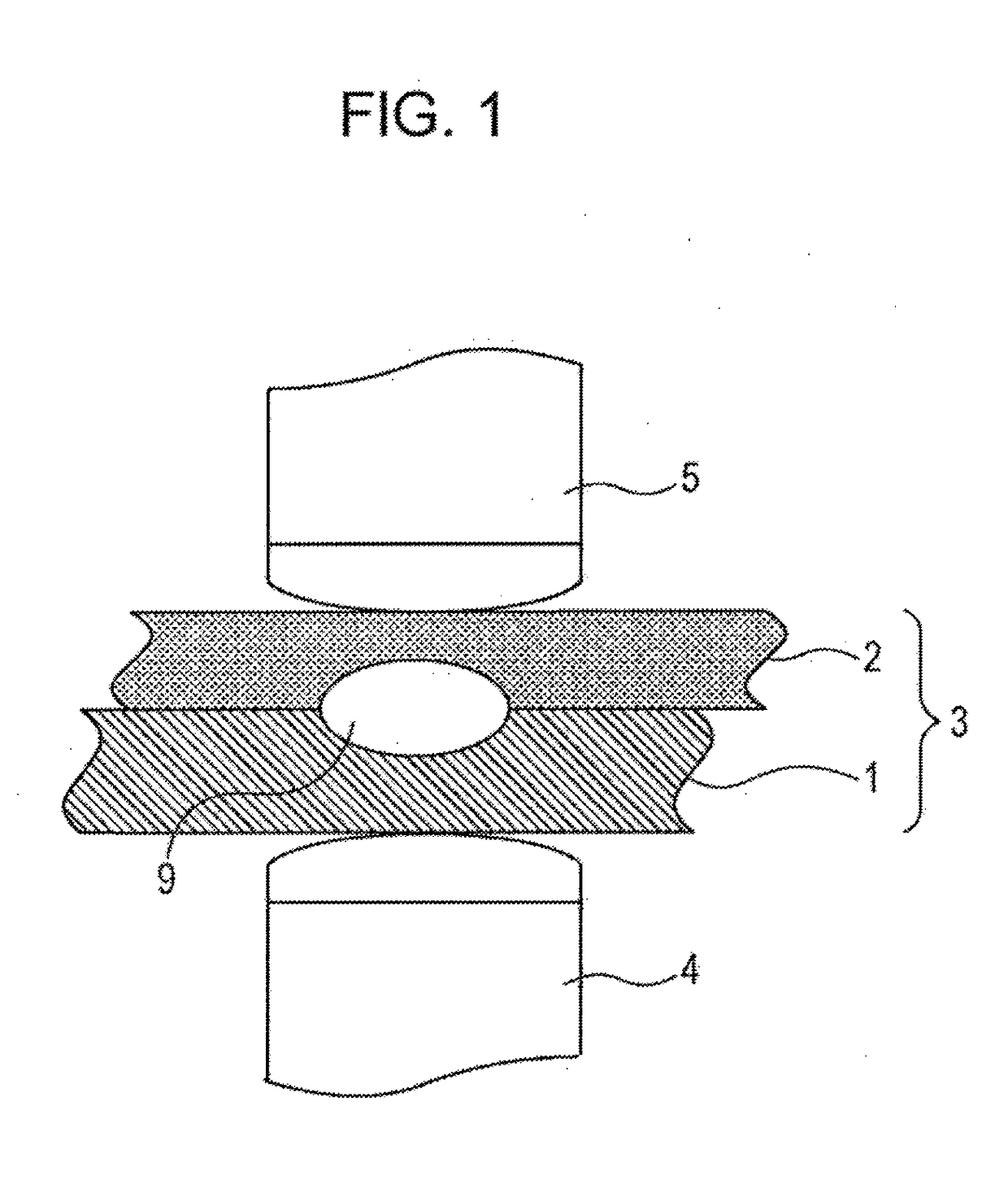
[0067]In Examples of the present invention, the device shown in FIG. 5 was used to produce a resistance spot-welded joint using a sheet set 3 including two overlapping hot-dip galvannealed steel sheets (a lower steel sheet 1 and an upper steel sheet 2). Specifically, the device used in the Examples was a welding device of the C gun type including a servo motor used to press the electrodes. The power source used was a DC power source.

[0068]In this case, the electric current was supplied under conditions shown in Table 1.

[0069]The electrodes 4 and 5 used were DR type electrodes made of alumina-dispersed copper and having a tip radius of curvature R of 40 mm and a tip diameter of 8 mm. The test pieces used were high-strength steel sheets having a 980 MPa-class tensile strength and sheet thicknesses of 0.8 to 2.6 mm and a high-strength steel sheet having a 1,470 MPa-class tensile strength and a sheet thickness of 2.0 mm. Two steel sheets of the same type and with the same thickness were...

example 2

[0074]In Examples of the present invention, a servo motor pressurizing-type resistance welding device attached to a C gun and including a DC power source was used to perform resistance spot welding on a sheet set including three overlapping hot-dip galvannealed steel sheets to thereby produce a resistance spot-welded joint.

[0075]In this case, the electric current was supplied under conditions shown in Table 2.

[0076]The electrodes 4 and 5 used were DR type electrodes made of alumina-dispersed copper and having a tip radius of curvature R of 40 mm and a tip diameter of 8 mm. The test pieces used were 980 MPa class high-strength steel sheets having sheet thicknesses of 0.8 to 2.3 mm and a 1,800 MPa class high-strength steel sheet having a sheet thickness of 1.2 mm. Three steel sheets of the same type and with the same thickness were stacked and welded.

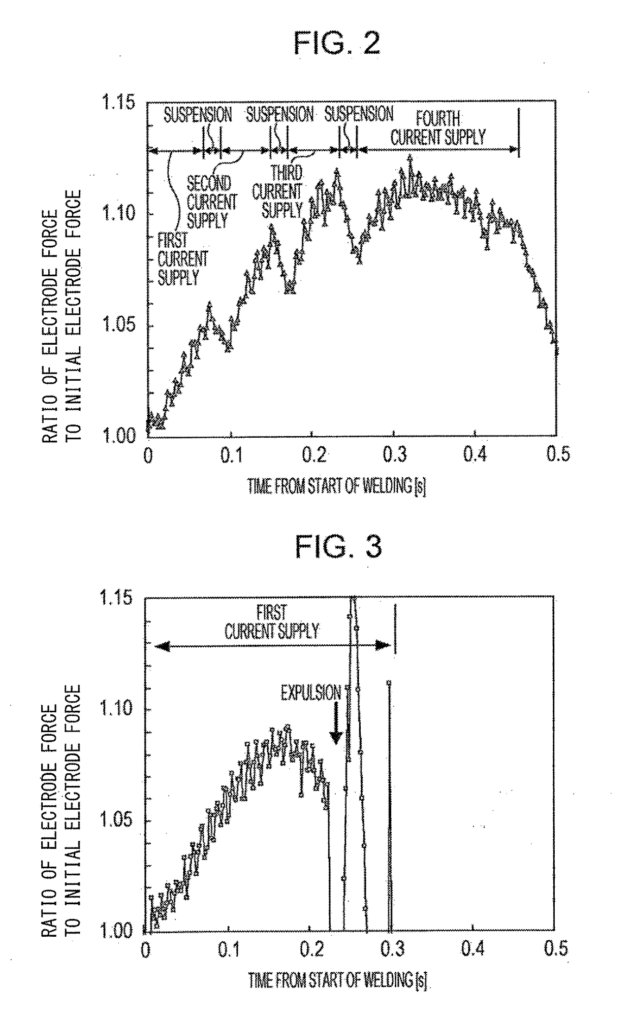
[0077]The electrode force during the electric current supply was measured using a strain gauge attached to the C gun. The electrode forc...


PUM

PropertyMeasurementUnit
Timeaaaaaaaaaa
Timeaaaaaaaaaa
Timeaaaaaaaaaa

Abstract

A resistance spot welding device for welding at least two overlapping steel sheets held between a pair of welding electrodes is provided. The resistance spot welding device includes the pair of electrodes, an electrode force gauge that measures an electrode force, and a controller that controls an electric current supply to the electrodes according to the electrode force measured by the electrode force gauge. The controller controls the electric current such that the electrode force F measured by the electrode force gauge after the start of the electric current supply is adjusted to a prescribed value.

Description

CROSS REFERENCE TO RELATED APPLICATIONS[0001]This is the U.S. National Phase application of PCT / JP2016 / 001174, filed Mar. 3, 2016, which claims priority to Japanese Patent Application No. 2015-043053, filed Mar. 5, 2015, and Japanese Patent Application No. 2015-071650, filed Mar. 31, 2015, the disclosures of these applications being incorporated herein by reference in their entireties for all purposes.TECHNICAL FIELD OF THE INVENTION[0002]The present invention relates to a resistance spot welding device for resistance spot welding, which is one type of lap resistance welding.BACKGROUND OF THE INVENTION[0003]To achieve an improvement in reliability of vehicle bodies and a reduction in weight of the vehicle bodies for the purpose of an improvement in fuel consumption, strengthening of steel sheets has been pursued in recent years. The use of high-strength steel sheets allows vehicle bodies to have stiffness comparable to that obtained using conventional steel even when the steel sheet...

Claims


Application Information

Patent Timeline
IPC IPC(8): B23K11/24B23K11/25B23K11/11
CPCB23K11/241B23K11/115B23K11/25B23K11/11B23K11/16B23K11/253B23K11/255B23K2101/006B23K2103/05B23K2103/04
Inventor TANIGUCHI, KOICHIOKITA, YASUAKIIKEDA, RINSEI
Owner JFE STEEL CORP
Why Eureka
Try Eureka