Casting device and casting method

A sprue and melt technology, applied in the direction of casting molds, casting mold components, casting equipment, etc., can solve problems such as inability to ensure, unfavorable operating material ratio or pouring quality

Inactive Publication Date: 2014-08-27
舒乐绞扭机有限责任公司
View PDF7 Cites 9 Cited by
  • Summary
  • Abstract
  • Description
  • Claims
  • Application Information

AI Technical Summary

Problems solved by technology

This disadvantageously increases the proportion of running material or the pouring quality, and the simultaneous start of the second casting phase cannot always be ensured

Method used


Image

  • Casting device and casting method

Examples


Embodiment Construction

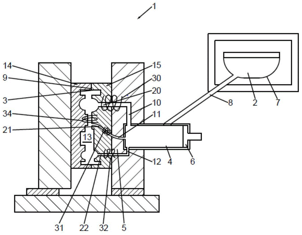
[0033] figure 1 A casting device 1 for injection casting of molten magnesium or aluminum is shown. The melt 2 is conducted from the melting furnace as storage container 7 via a feed line 8 into a filling chamber 4 . The filling chamber 4 forms a store for a predetermined quantity of melt 2 . The melt 2 can leave the filling chamber 4 via a plurality of sprues 11 , 12 , 13 and flow into a mold cavity 3 . The mold cavity 3 is formed by the two casting mold half-shells 14 , 15 as a hollow space 13 and forms, in a known manner, a negative mold enlarged with shrinkage (Schwindma β) of the die-cast product to be produced. The two casting mold half-shells 14 , 15 have a vertical parting face 9 for later removal of the casting.

[0034] Filling chamber 4 is filled with a metered quantity of melt 2 in the first casting phase. Precise metering ensures that the mold cavity 3 is later completely filled and that the resulting casting waste is not broken.

[0035] The casting piston 6 ...


PUM


Abstract

The invention relates to a direct electromagnetic casting driving apparatus (1) and a method of manufacturing a cast component through a plurality of casting channels (10, 11, 12). Different solution channels (20, 21, 22) in the casting channels (10, 11, 12) are heated, braked or accelerated in different degrees by means of the electromagnetic fields of electrified coils (30, 31, 32, 33). A non-contact feed is also provided. Required casting driving force is reduced. The invention ensures controllable starting of a second casting step and reverse action on edge layer solification. Meanwhile, the running material is reduced and the injection weight is minimized.

Description

technical field [0001] The invention relates to a method for the production of cast components using a casting device, in which a molten metal is introduced in a flowable state from a filling chamber through sprues into a mold cavity with a hollow space, and Here, the sprues have different lengths or different cross sections. The invention also relates to a device for carrying out the method. Background technique [0002] A molten metal, usually in the form of a liquid alloy, is provided for forming metal cast parts. The melt is intermediately stored in a filling chamber as a storage device and is held there in a liquid state by the input of heat. Via a pouring unit, the melt reaches a mold cavity, which is the negative mold for the cast part to be cast. [0003] An important criterion for high-quality cast products is the undisturbed, gas-free and homogeneous feeding of the liquid melt. For the homogeneous delivery of the melt, electromagnetic pumps are known, for examp...

Claims


Application Information

Patent Timeline
Patent Type & Authority Applications(China)
IPC IPC(8): B22C9/08
CPCB22D35/04B22D17/10B22D17/32B22D18/08B22D17/30B22D45/00B22D17/2272B22D27/02
Inventor T·施瓦茨
Owner 舒乐绞扭机有限责任公司
Why Eureka
Try Eureka