Laser welding device

A laser welding and laser technology, used in laser welding equipment, welding equipment, metal processing equipment, etc., can solve the problems of temperature cannot be selectively controlled, cannot use reflow welding, etc., to ensure the consistency of quality and appearance, avoid Contact welding surface, high welding efficiency

Active Publication Date: 2016-03-02
KUNSHAN LIANTAO ELECTRONICS CO LTD
View PDF9 Cites 0 Cited by
  • Summary
  • Abstract
  • Description
  • Claims
  • Application Information

AI Technical Summary

Problems solved by technology

The main advantage of reflow soldering lies in the soldering of chip components, but more and more components are temperature-sensitive components, and the temperature cannot be selectively controlled by reflow soldering, and the existence of a large number of plug-in components cannot Using reflow soldering technology

Method used


Image

  • Laser welding device
  • Laser welding device
  • Laser welding device

Examples


Embodiment Construction

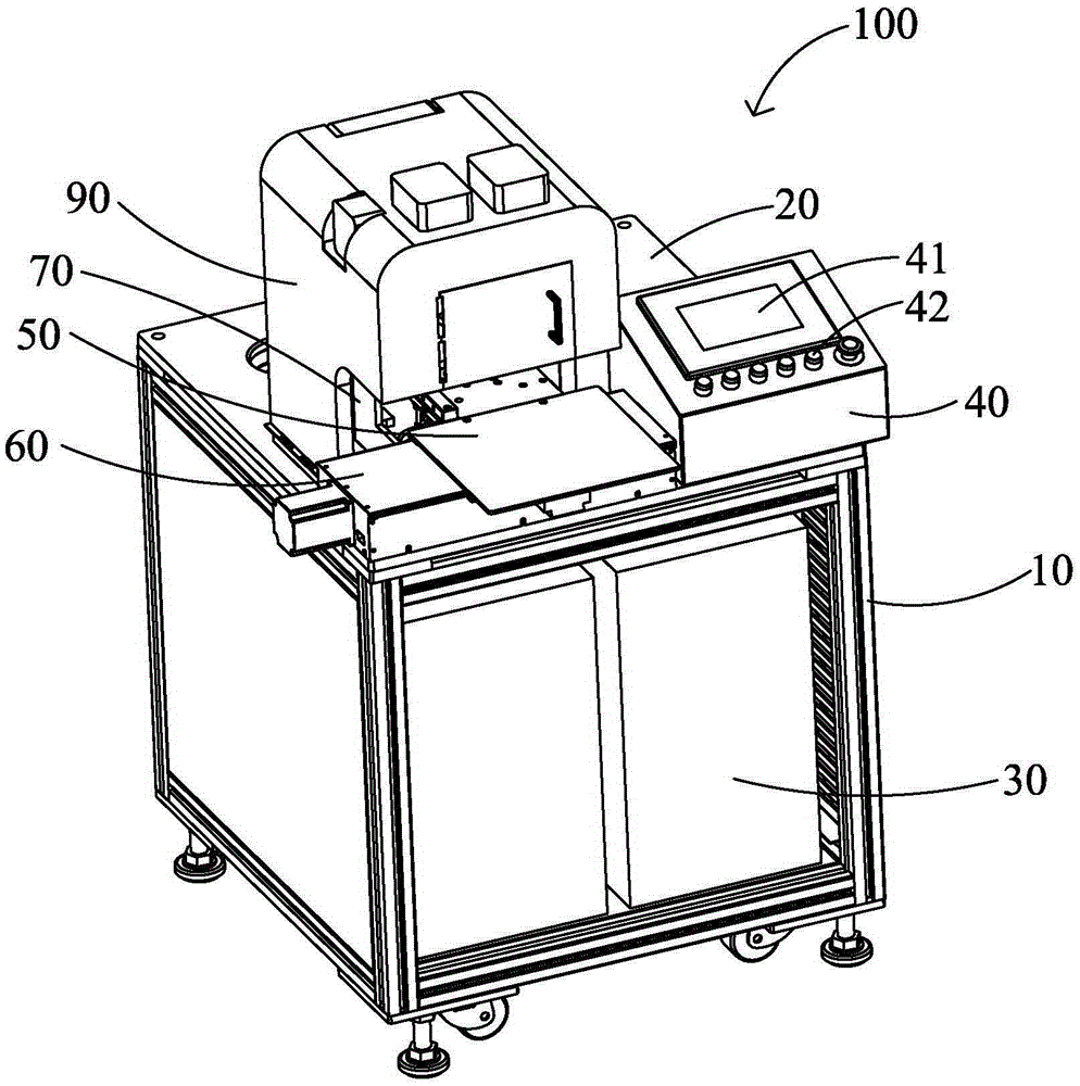
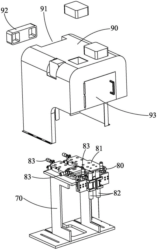
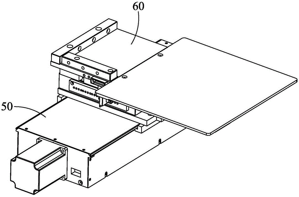
[0014] see Figure 1 to Figure 5 As shown, the present invention provides a laser welding device 100, which includes a work frame 10, a workbench 20, a laser generator 30, a control box 40, a feeding mechanism 50, a discharging mechanism 60, a bracket 70, a laser mechanism 80, and a protective Cover 90.

[0015] The workbench 20 is supported on the top of the work frame 10 , and the laser generator 30 is installed in the work frame 10 and connected with the laser mechanism 80 . The control box 40 , the feeding mechanism 50 and the bracket 70 are installed on the workbench 20 respectively. The discharging mechanism 60 is installed on the top of the feeding mechanism 50 . Laser Mechanism The laser mechanism 80 is installed on the bracket 70 , and the protective cover 90 is also installed on the bracket 70 and covers the laser mechanism 80 .

[0016] A control panel 41 and control buttons 42 are arranged on the top of the control box 40 , and the operator operates through the ...


PUM


Abstract

The invention relates to a laser welding device. The laser welding device comprises a working frame, a working platform, a lager generator, a control box, a feeding mechanism, a placing mechanism, a support and a laser mechanism; the working platform is arranged on the working frame in a supporting mode; the laser generator which is installed inside the working frame is connected with the laser mechanism; the control box, the feeding mechanism and the support are installed on the working platform; the laser mechanism is installed on the support; the laser mechanism is provided with a lens cylinder; the placing mechanism is installed at the top of the feeding mechanism; the feeding mechanism is provided with a first motor which drives the placing mechanism to move horizontally; the placing mechanism is provided with a placing carrier which can place materials and a second motor which drives the placing carrier to move forward and backward; the laser welding device is high in welding efficiency and applicable to production in a large scale.

Description

technical field [0001] The invention relates to a welding processing device, in particular to a laser welding device. Background technique [0002] Modern electronic product production, optical communication, household appliances and many other fields require circuit boards to provide control and signal units. With the miniaturization of electronic components and the use of a large number of integrated circuits, solder joints are getting smaller and smaller, and the distance between solder joints The spacing is also getting smaller and smaller, which puts forward higher and higher requirements for the soldering of circuit board components. [0003] At present, welding machines mainly include resistance welding machines and reflow welding machines. The resistance welding machine uses a resistance head made of a material with a large resistance value, which is heated under the action of current, and then achieves the purpose of welding by contacting the material of the solder...

Claims


Application Information

Patent Timeline
Patent Type & Authority Patents(China)
IPC IPC(8): B23K26/21B23K26/70
CPCB23K26/083B23K26/20
Inventor 周智张军
Owner KUNSHAN LIANTAO ELECTRONICS CO LTD
Why Eureka
Try Eureka