
Folding mobile phone satellite structure

A mobile phone satellite and foldable technology, applied in the field of aerospace applications, can solve problems such as short working hours and electromagnetic interference, and achieve the effect of increasing the area, reducing the horizontal size, and reducing electromagnetic interference

Inactive Publication Date: 2014-08-27
NORTHWESTERN POLYTECHNICAL UNIV
View PDF7 Cites 12 Cited by
  • Summary
  • Abstract
  • Description
  • Claims
  • Application Information

AI Technical Summary

Problems solved by technology

[0007] The purpose of the present invention is to design a foldable mobile phone satellite structure for the current mobile phone satellites with simple functions, short working hours and serious internal electromagnetic interference. The design coupling problem between them, and this structure is convenient for launch and transportation, and can effectively reduce electromagnetic interference
[0008] The technical problem that the present invention solves is: design a kind of foldable mobile phone satellite structure, realize the installation and fixation to mobile phone satellite equipment, and protect mobile phone satellite to work safely in the task cycle; Strict restrictions lead to problems such as simple tasks and short working hours; through modular design, the versatility of the foldable mobile phone satellite structure is enhanced, making it suitable for various tasks; the problem of serious electromagnetic interference inside the current mobile phone satellite is overcome, and flexible printing is used The board is connected to the internal circuit of the foldable mobile phone satellite structure, which greatly simplifies the internal circuit and ensures the reliability of the foldable mobile phone satellite structure.

Method used


Image

  • Folding mobile phone satellite structure
  • Folding mobile phone satellite structure
  • Folding mobile phone satellite structure

Examples


Embodiment Construction

[0024] The technical solutions of the present invention will be further described below in conjunction with specific implementation examples.

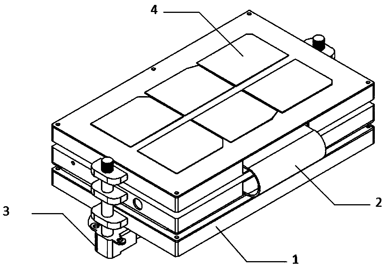
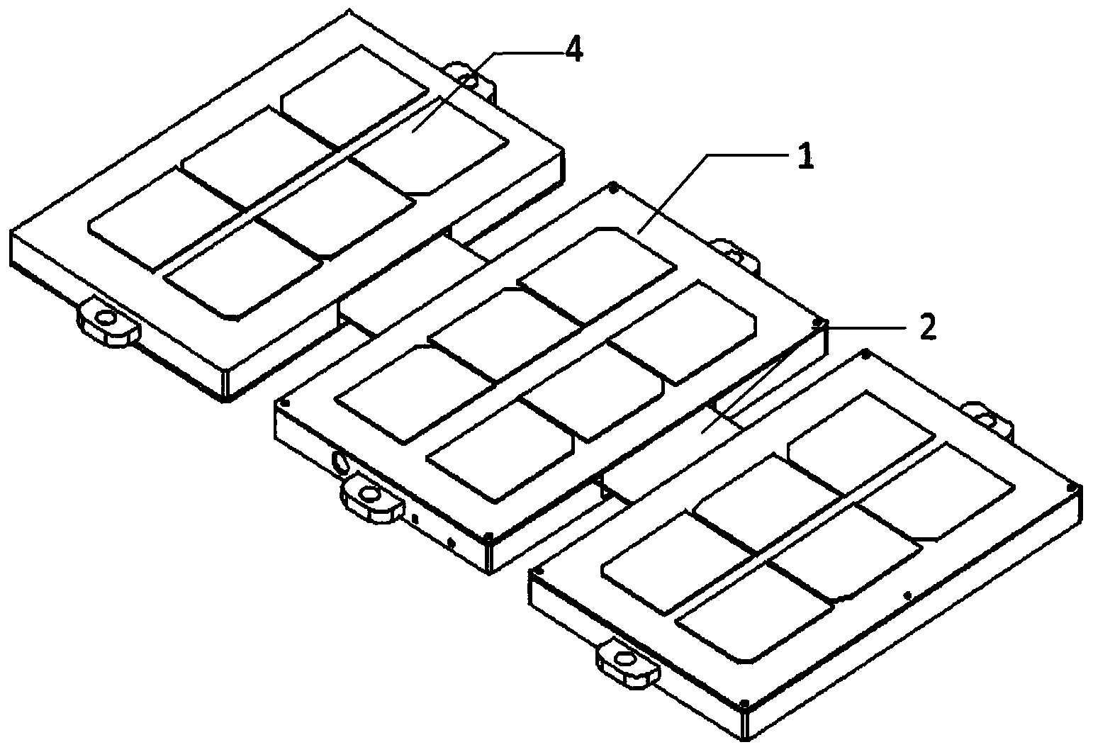
[0025] 1. see Figure 1-Figure 7 , the present invention designs a foldable mobile phone satellite structure, which mainly includes: a sub-system installation box 1, a flexible printed board 2, a pull-out bolt 3, satellite platform equipment, and the satellite platform equipment is integrated into a communication board 8, an integrated electronic board 9. Power board 10.

[0026] 2. see Figure 4 , The foldable mobile phone satellite adopts a modular design, and the mobile phone satellite platform equipment is integrated into three subsystem function boards, and the subsystem function boards are installed into the subsystem installation box 1 through screws.

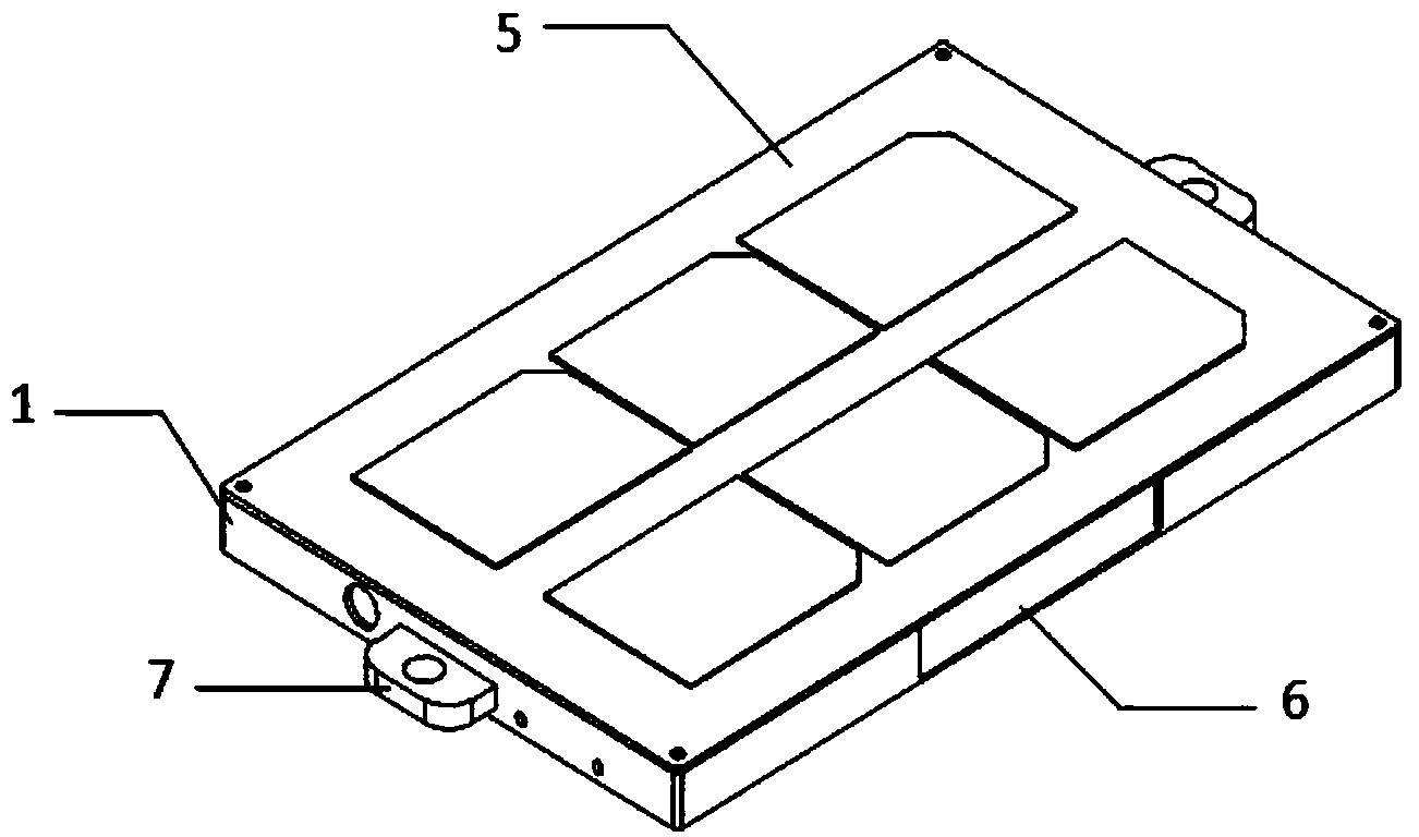
[0027] 3. see figure 1 and image 3 , the upper surface 5 of the subsystem installation box is designed as a detachable structure, so as to facilitate the installation and op...


PUM


Abstract

The invention relates to a mobile phone satellite structure in the spaceflight field, in particular to a folding mobile phone satellite structure. The problems that an existing mobile phone satellite is simple in function, short in work time and serious in internal electromagnetic interference are solved. According to the technical scheme, the folding mobile phone satellite structure mainly comprises a mobile phone satellite platform device, sub-system installing boxes, a locking part and an unfolding part; the mobile phone satellite platform device is composed of a plurality of integrated sub-system function plates, and each sub-system function plate is arranged in the corresponding sub-system installing box and achieves folding and unfolding through the locking part and the unfolding part. The folding mobile phone satellite structure has universality, the mobile phone satellite platform device can be redesigned according to specific requirements, and a satellite can be quickly assembled through the structure. The size of the main structure of the folding mobile phone satellite can be adjusted conveniently through changing the number of the sub-system function plates and the number of the installing boxes, and tasks of different complexity levels are achieved.

Description

technical field [0001] The invention belongs to the field of aerospace applications, and relates to a mobile phone satellite structure, in particular to a foldable mobile phone satellite structure. Background technique [0002] Mobile satellites refer to the direct use of smartphone components to assemble low-cost micro-satellites. Mobile satellites will open up a new field and leverage non-aerospace hardware and software to enter the space field. [0003] At present, many institutions, including NASA of the United States and SSTL of the United Kingdom, have carried out research on mobile phone satellites. [0004] In order to verify whether the processor of the mobile phone can work in space, Surrey Satellite Technology Co., Ltd. of the United Kingdom loaded a modified Nexus-one smartphone on its STRaND-1 satellite launched in 2013. Although this task was unsuccessful, But STRaND-1 is still being called the world's first mobile phone satellite in orbit. [0005] NASA Ames...

Claims


Application Information

Patent Timeline
Patent Type & Authority Applications(China)
IPC IPC(8): B64G1/42B64G1/00
Inventor 龚春林吴小萌谷良贤朱海珍
Owner NORTHWESTERN POLYTECHNICAL UNIV
Learn More