Flat plate rammer compactor and construction technology for ramming concrete of roller-compacted concrete gravity dam

A technology of roller compacted concrete and tamping machine, which is applied in the treatment of gravity dams, dams, and building materials, and can solve problems such as the inability to roll compacted concrete in roller compacted construction, so as to reduce the amount of pouring work, reduce the failure rate, and have small working resistance Effect

Active Publication Date: 2014-08-27
SINOHYDRO BUREAU 16 CO LTD
View PDF7 Cites 2 Cited by
  • Summary
  • Abstract
  • Description
  • Claims
  • Application Information

AI Technical Summary

Problems solved by technology

[0003] The purpose of the present invention is to solve the difficulty that traditional vibrating roller equipment cannot carry out rolling construction on the roller compacted concrete within 1m of the dam's u

Method used


Image

  • Flat plate rammer compactor and construction technology for ramming concrete of roller-compacted concrete gravity dam
  • Flat plate rammer compactor and construction technology for ramming concrete of roller-compacted concrete gravity dam
  • Flat plate rammer compactor and construction technology for ramming concrete of roller-compacted concrete gravity dam

Examples


Example Embodiment

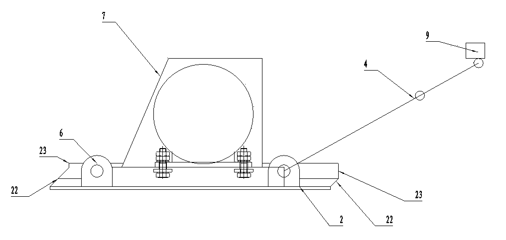
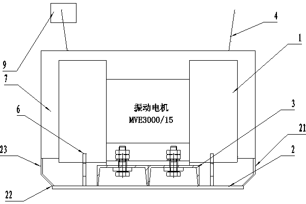
[0028] Example 1, such as Figure 1-2 As shown, a plate compactor is mainly composed of a vibration motor 1, a ram plate 2, a base 3, a handrail 4, a protective cover 5, and a control switch 9. The ram plate 2 is fixed under the base 3, and the vibration motor 1 is fixed Above the base 3, a protective cover 5 is fixed outside the vibrating motor 1, the armrest 4 is outside the protective cover 5, and the size of the ram is 80-100×50-70 cm. In this embodiment, the size of the ram plate is selected as 90 cm×60 cm. A surrounding edge 21 is fixed around the ram plate 2. The surrounding edge 21 is composed of an inclined surface 22 and a vertical surface 23. The inclined surface 22 is connected to the ram plate 2, that is, the inclined surface 22 is connected between the vertical surface 23 and the ram plate 2, and the front end is inclined toward The fuselage is tilted inward, the inclined surface 22 and the ram plate 2 form an acute angle, and the acute angle is less than 53°. Th...


PUM


Abstract

A flat plate rammer compactor is mainly composed of a vibration motor, a ramming plate, a base, handrails, a protective cover and a control switch. The ramming plate is fixedly arranged below the base, the vibration motor is fixedly arranged above the base, the protective cover is fixedly arranged outside the vibration motor, and the handrails are arranged outside the protective cover. The flat plate rammer compactor is structurally characterized in that surrounding edges are fixedly arranged around the ramming plate, the surrounding edges are composed of inclined faces and vertical faces, the inclined faces are connected between the vertical faces and the ramming plate, the inclined faces at the front end are inclined towards the interior of a machine body, acute angles are formed between the inclined faces and the ramming plate, according to the height difference between the protective cover and the base, the length of the front end, stretching out of the protective cover, of the ramming plate is smaller than or equal to 1:0.75, and the control switch is arranged on the handrail on one side. The flat plate rammer compactor has the advantages that the structure is simple, manufacturing is easy, work efficiency is high, the fault rate is reduced, the flat plate rammer compactor is especially suitable for positions where a vibration roller cannot carry out concrete ramming construction on an upstream side formwork and a downstream side formwork of a dam and the periphery of a bank slope, pouring construction on distorted concrete in traditional construction can be effectively reduced, and the process of replacing the manual operation is achieved.

Description

technical field [0001] The invention belongs to concrete compaction equipment, in particular to dam roller compacted concrete compaction equipment. Background technique [0002] At present, during the construction of roller compacted concrete gravity dams in China within 1m of the dam’s upstream and downstream formwork and the surrounding slope, there are problems that vibrating rollers cannot be used for direct rolling construction, and manual spreading is required. The metamorphic concrete construction technology of cleaning slurry and vibrating. This construction process not only increases the construction process and reduces the construction progress, but also greatly increases the construction cost of concrete. Since the lower part of the dam is inclined, the slope is mostly 1:0.75, and the current tamping machines all work on a completely open plane, without considering that when the formwork is inclined, the angle formed between the formwork and the tamping surface w...

Claims


Application Information

Patent Timeline
IPC IPC(8): E02B7/10E04G21/06
Inventor 吴秀荣吴友旺黄宗元娄海
Owner SINOHYDRO BUREAU 16 CO LTD
Why Eureka
Try Eureka