An independent current sharing circuit suitable for multi-channel parallel LED strings

A circuit and current sharing technology, which is applied in the layout of electric lamp circuits, electric light sources, electrical components, etc., can solve the problems of uneven current, different V-I characteristics of multiple LED strings, and the inability to achieve independent current sharing of circuits, and achieve a simple structure. , The effect of efficient and autonomous current sharing

Active Publication Date: 2016-06-29
NANJING UNIV OF AERONAUTICS & ASTRONAUTICS
View PDF2 Cites 0 Cited by
  • Summary
  • Abstract
  • Description
  • Claims
  • Application Information

AI Technical Summary

Problems solved by technology

[0006] The present invention aims to realize autonomous current sharing among multiple parallel LED strings, and solve the phenomenon of current unevenness caused by different V-I characteristics of multiple LED strings, but the existing current sharing scheme cannot realize autonomous current sharing of circuits

Method used


Image

  • An independent current sharing circuit suitable for multi-channel parallel LED strings
  • An independent current sharing circuit suitable for multi-channel parallel LED strings
  • An independent current sharing circuit suitable for multi-channel parallel LED strings

Examples


Embodiment 1

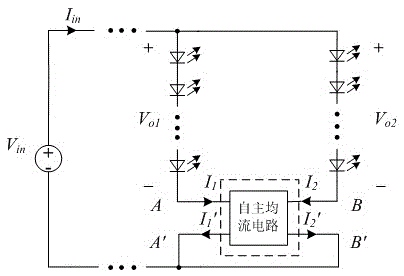
[0026] The schematic diagram of the independent current equalizing circuit of the present invention is as attached figure 1 , 3 Shown:

[0027] 1) pair attached figure 1 In the circuit shown, when the two currents are uneven, there must be a potential difference between A and B (at this time, when there is no independent current equalizing circuit control, the schematic diagram of the V-I characteristic curve of the two LED strings is as attached Image 6 shown). attached figure 1 The two potentials of points A and B correspond to the attached image 3 Middle port A, B potential;

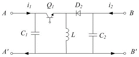
[0028] 2) The present invention is attached to the traditional Buck-Boost circuit figure 2 improved on the basis of figure 2 The independent current equalizing circuit is composed of capacitors C1, C2, inductor L, diode D2 and switch tube Q1. It can only realize the one-way power transmission function of one port input and one port output. According to this working principle, if the D2 b...

Embodiment 2

[0038] The present invention can also adopt as attached Figure 4 In the circuit design shown, in order to control the working state of the Buck-Boost circuit and realize two-way current sharing, it is necessary to measure the voltage across the capacitors C3 and C4 at the same time.

[0039] 1) The example is attached image 3 On the basis of the circuit, in order to collect the potential information of ports A and B, a circuit is connected between the two ports, in which C3 and D3 are connected in series, D4 and C4 are connected in series, and the two series branches are connected in parallel to form the circuit, as shown in the attached Figure 4 As shown, when the circuit is working, the working state of the circuit is controlled with the voltage at both ends of C3 and C4 as a reference;

[0040] 2) As attached image 3 As shown, when the potential of port A is high, D3 is turned on, D4 is turned off, C3 stores energy, and the voltage at both ends of C3 is positive. The ...

Embodiment 3

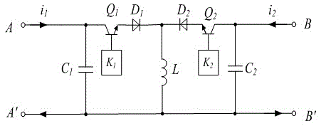
[0044] The present invention can also adopt as attached Figure 5 The autonomous current sharing circuit shown can realize autonomous current sharing by collecting the potentials of the two ports of the Buck-Boost circuit.

[0045] 1) Different from Embodiment 2, when the autonomous current sharing circuit is working, it can directly collect the potentials of ports A and B for comparison, and the two ports are respectively connected to the input terminals of the voltage comparator, and the voltage comparator generates level signals to switches K1 and K2 The tube controller, the switch tube controller finally runs the drive unit, thereby controlling the working status of Q1 and Q2;

[0046] 2) When the two currents are uneven, the voltage signal must be high or low. When the measured potential of the A terminal is high, the voltage comparator sends a signal to the controller K1, and the switch tube controller K1 controls Q1 to work in the switch state, duty The ratio is 0.5, a...


PUM


Abstract

The present invention is an autonomous current sharing circuit suitable for multi-channel parallel LED strings, the autonomous current sharing circuit includes capacitors C1, C2, inductor L, diodes D1, D2, switching tubes Q1, Q2, and a switching tube controller K1, K2, the switching tube Q1 and the diode D1 form a series branch, one end of the switching tube Q1 is connected to the capacitor C1, the other end is connected to the anode of the diode D1, the cathode of the diode D1 is connected to the inductor L and connected to the cathode of the diode D2, D2 and Q2 In series, the anode of D2 is connected to one end of the switch, the other end of Q2 is connected to C2, and the free terminals of C1, L, and C2 are connected to each other to form a common port; the control pins of Q1 and Q2 are respectively connected to the switch tube controllers K1 and K2. Its power part is composed of a bidirectional Buck-Boost circuit, which can realize independent current sharing between two (groups) parallel LED strings, greatly enhancing the reliability of LED work.

Description

technical field [0001] The invention relates to an autonomous current sharing circuit unit suitable for multiple LED strings connected in parallel, and belongs to the field of lighting and electric energy conversion. Background technique [0002] Light-emitting diode (LED) has the advantages of good luminous energy efficiency, good optical performance, long life and environmental friendliness. It is a new generation of green lighting source with great development prospects. [0003] Due to the low power and low brightness of LEDs, it is an inevitable measure to connect multiple LEDs in series or parallel in the occasions where high brightness is required. In order to ensure the same brightness of multiple LEDs, they are usually connected in series. The number of LEDs in series is affected by the LED driving voltage. Therefore, in applications that require more LEDs, a series-parallel connection is generally used. However, due to the different V-I characteristics of differen...

Claims


Application Information

Patent Timeline
Patent Type & Authority Patents(China)
IPC IPC(8): H02M3/156H05B37/02
Inventor 任小永顾云波阮新波陈乾宏
Owner NANJING UNIV OF AERONAUTICS & ASTRONAUTICS
Why Eureka
Try Eureka