
Housing for field device

A field device and shell technology, applied in the direction of support structure installation, magnetic field/electric field shielding, electrical components, etc., can solve the problems of logistics consumption, material considerations, pollutant accumulation, etc., and achieve the effect of reducing time

Active Publication Date: 2014-08-27
ENDRESS HAUSER INC
View PDF6 Cites 0 Cited by
  • Summary
  • Abstract
  • Description
  • Claims
  • Application Information

AI Technical Summary

Problems solved by technology

The corresponding additional parts bring the following disadvantages: logistical effort, material considerations, assembly effort, sealing problems, additional expense and time-consuming, ugly appearance, risk of contamination accumulation, risk of damage, etc.

Method used


Image

  • Housing for field device
  • Housing for field device

Examples


Embodiment Construction

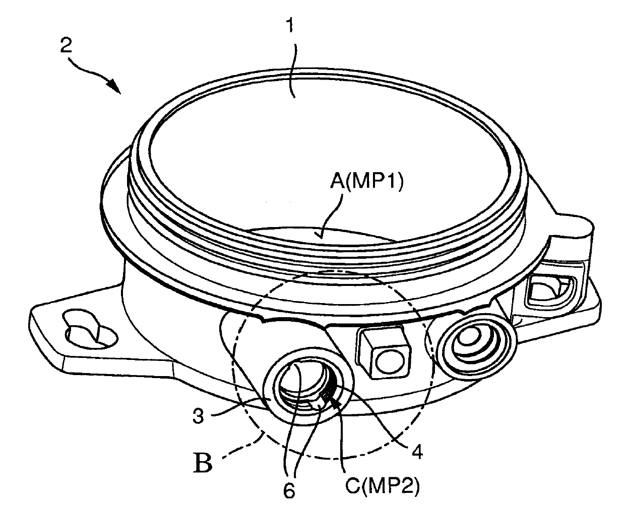
[0026] Housing 2 for field devices (not in figure 1 separately illustrated) for accommodating an electronic unit (not shown). The sensor unit for determining and / or monitoring process variables in automation technology is attached directly to the housing 2 (compact sensor), or the sensor unit and electronics unit are implemented separately and connected via cables. The housing 2 is substantially pot-shaped and manufactured from a non-conductive material. In particular, the housing 2 consists of a synthetic material, such as plastic or composite material.

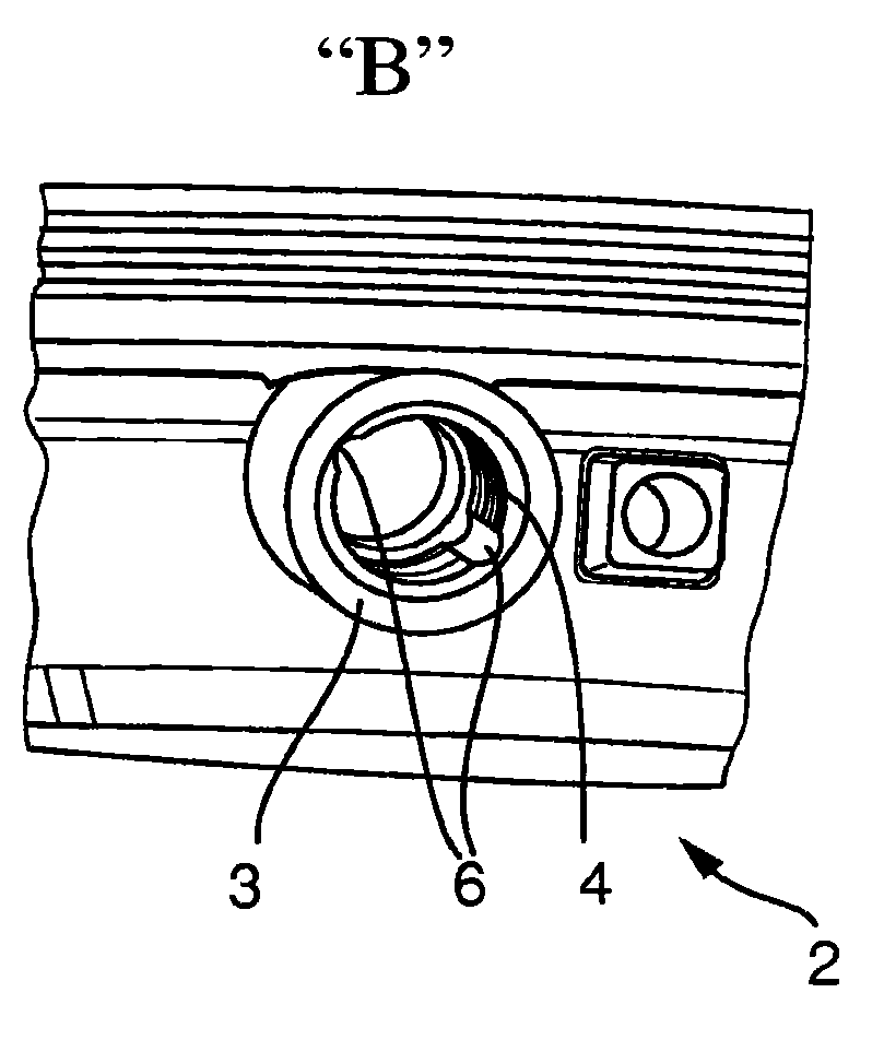
[0027] refer to figure 1 , The wire guide channel 3 is set on the shell 2. The wire guide channel 3 has an internal thread 4 . Of course, the following statements are also valid in the case of external threads. In the illustrated case, the inner surface of the housing 2 and the inner surface of the wire guide channel 3 in the region of the thread 4 are provided with an electrically conductive coating 5 . In this case, ...


PUM


Abstract

A field device with a housing for accommodating an electronics unit. The housing is pot shaped and composed of a non-conductive material, wherein at least one line guide passageway with a screw thread is provided on the housing, wherein the line guide passageway is provided with a conductive coating in the region of the thread, and wherein the screw thread has at least one groove in at least one region extending in the axial direction of the line guide passageway.

Description

technical field [0001] The invention relates to a field device with a housing for accommodating an electronics unit, wherein the housing is pot-shaped and consists of a non-conductive material, wherein at least one threaded wire guide channel is provided on the housing, and wherein The wire guide channel is provided with an electrically conductive coating in the region of the thread. In particular, the invention relates to field devices in automation technology for determining or monitoring physical or chemical process variables. Background technique [0002] In automation technology, especially in process and manufacturing automation technology, field devices are often used for recording and / or influencing process variables. For recording process variables are sensors such as, for example, filling degree measuring devices, flow measuring devices, pressure and temperature measuring devices, pH-oxidation-reduction potential measuring devices, conductivity measuring devices, ...

Claims


Application Information

Patent Timeline
Patent Type & Authority Applications(China)
IPC IPC(8): H05K9/00H05K7/14H02G3/08
CPCH05K9/0045H05K7/14H02G3/083H05K5/0247
Inventor 伊万·米尔恰·波尔
Owner ENDRESS HAUSER INC
Learn More