Evaporator heat exchanger tube box welding structure and manufacturing method

A technology of heat exchanger tubes and welded structures, which is applied to evaporator accessories and other directions to reduce costs, simplify the operation of blanking and welding, and improve quality and reliability.

Inactive Publication Date: 2014-09-03
JIANGSU JIATAI EVAPORATION CRYSTALLIZATION EQUIP
View PDF0 Cites 2 Cited by
  • Summary
  • Abstract
  • Description
  • Claims
  • Application Information

AI Technical Summary

Problems solved by technology

[0003] Since the applicant introduced technical means such as forced circulation and continuous discharge in the evaporator crystallization equipment to solve technical problems such as scaling and clogging, higher requirements were put forward for the treatment concentration and treatment efficiency of the evaporator heat exchanger , if the flow of the tube box is increased in the form of baffles, the splicing and welding seam of the existing oval head and baffles puts forward very high requirements for blanking and welding, and has become an evaporator heat exchanger manufacturing bottleneck in

Method used


Image

  • Evaporator heat exchanger tube box welding structure and manufacturing method
  • Evaporator heat exchanger tube box welding structure and manufacturing method
  • Evaporator heat exchanger tube box welding structure and manufacturing method

Examples


Embodiment

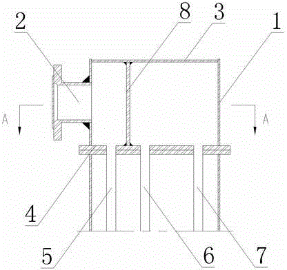
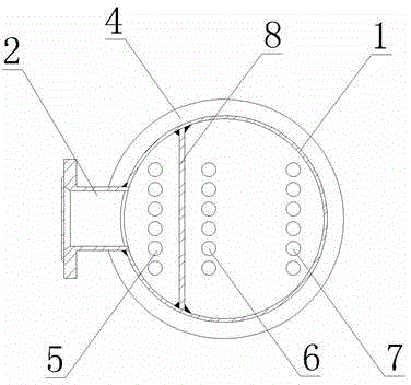
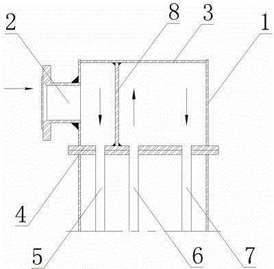
[0019] Embodiment: The welding structure of the evaporator heat exchanger tube box of this embodiment is as figure 1 with figure 2 As shown, it includes a vertical cylindrical barrel 1, on the side wall of the barrel 1, there is a feed port 2 for inputting the material to be processed, and a flat bottom head 3 is welded on the top of the barrel 1. The bottom of the body 1 is welded with a tube plate 4, and the lower part of the tube plate 4 is in communication with the first heating tube 5, the second heating tube 6 and the third heating tube 7. In order to facilitate segmented manufacturing and splicing installation, the edge of the tube sheet 4 extends to the outside of the cylinder 1 and forms a flange.

[0020] A baffle 8 is welded in the cylinder 1, and the baffle 8 is a vertical rectangular plate. Its two sides are connected with the vertical inner wall of the cylinder 1, and its top edge is connected with the flat-bottomed head 3. The bottom edge is connected with the tub...


PUM


Abstract

The invention discloses an evaporator heat exchanger tube box welding structure and a manufacturing method. The structure comprises a barrel with a feeding hole in the side wall, wherein a flat bottom head and a tube plate are welded at the two ends of the barrel respectively; a first heating tube, a second heating tube and a third heating tube are communicated below the tube plate; a baffle plate in the barrel separates the barrel into a first chamber and a second chamber; the first chamber is communicated with the feeding hole and the first heating tube; the second chamber is communicated with the second and third heating tubes. The manufacturing method comprises the step of welding the barrel, the tube plate, the baffle plate and the flat bottom head in sequence. The evaporator heat exchanger tube box welding structure and the manufacturing method are beneficial for forming a tube box, are more convenient for welding and are more beneficial for space distribution after baffling.

Description

Technical field [0001] The invention relates to a component of an evaporation crystallization device and a manufacturing method, in particular to a welding structure and a manufacturing method of an evaporator heat exchanger tube box. Background technique [0002] The working pressure of the evaporator heat exchanger is about 0.3Mpa, and the flowing medium is usually highly corrosive salty sewage. The conventional design in the chemical industry is the structure of a barrel-shaped container, and its end adopts a stamped and formed oval head , On the one hand, the elliptical head has strong pressure resistance, and the splicing seam between the head and the cylinder is also convenient to use the flat welding method on the rolling frame. [0003] Since the applicant introduced forced circulation and continuous discharging in the evaporator crystallization equipment to solve technical problems such as fouling and blockage, it also puts forward higher requirements on the processing con...

Claims


Application Information

Patent Timeline
Patent Type & Authority Applications(China)
IPC IPC(8): B01D1/30
Inventor 树晓荣
Owner JIANGSU JIATAI EVAPORATION CRYSTALLIZATION EQUIP
Why Eureka
Try Eureka