
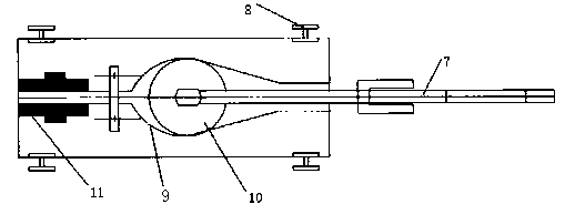
Precise tube drawing machine

A technology of pipe drawing machine and stand, applied in the field of precise automatic pipe drawing, can solve the problems of low pipe rolling precision, low efficiency and large material loss, etc.

Active Publication Date: 2014-09-03
DONGQING TECH
View PDF6 Cites 2 Cited by
  • Summary
  • Abstract
  • Description
  • Claims
  • Application Information

AI Technical Summary

Problems solved by technology

The advantage of rolled pipe is that the quality of the inner and outer surfaces is high, and the mechanical properties are stable after solid solution treatment; the disadvantage is that the size of the rolled pipe is difficult to make too small, usually it is difficult to achieve a capillary below 6mm, and the other is the quality of the rolled pipe. The precision is low. For example, the outer diameter is 6mm, and the corresponding tolerance is difficult to control within ±0.02mm. In addition, the rolling efficiency is low, the production cycle is long, etc.
The advantage of tube drawing is that it has high dimensional accuracy and can be used to make capillary tubes with extremely small diameters. Usually, capillaries with an outer diameter of 0.3mm or more can be drawn, and special-shaped products can be drawn, etc. The disadvantages are high requirements for molds and difficult control of inner surface quality. , material loss, etc.
[0003] The main one of the current pipe drawing methods is the straight drawing method, which is to draw a pipe less than the length of the equipment in a fixed-length pipe drawing equipment. The advantage is that the precision is very high, and the disadvantage is that the efficiency is low. The stretching equipment used in the tube-drawing method is usually a cylinder. The cylinder not only consumes a lot of energy, but also has a low efficiency. Every time the tube is drawn, the air pump needs to be refilled.

Method used


Image

  • Precise tube drawing machine
  • Precise tube drawing machine
  • Precise tube drawing machine

Examples


Embodiment Construction

[0015] Embodiments of the present invention are described in detail below, examples of which are shown in the drawings, wherein the same or similar reference numerals designate the same or similar elements or elements having the same or similar functions throughout. The embodiments described below by referring to the figures are exemplary only for explaining the present invention and should not be construed as limiting the present invention.

[0016] In the description of the present invention, unless otherwise specified and limited, it should be noted that the terms "installation", "connection" and "connection" should be understood in a broad sense, for example, it can be mechanical connection or electrical connection, or two The internal communication of a component can be directly connected or indirectly connected through an intermediary. Those of ordinary skill in the art can understand the specific meanings of the above terms according to specific situations.

[0017] ...


PUM


Abstract

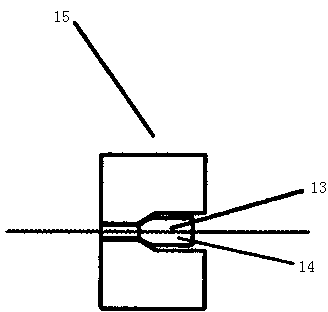
The invention designs a precise tube drawing machine. The precise tube drawing machine comprises a cam trolley, wherein wheels of the trolley are arranged on guide rails at the two sides of a transmission chain; a cam groove is formed in the center of the trolley; the cam groove is internally provided with a cam; the front side of the cam is connected with a pull rod; the head of the pull rod is bent downwards to form a downward hook; the back side of the cam is provided with clamping blocks for clamping a material to be processed; when the cam moves frontwards, the clamping blocks are at a clamped state; when the cam moves backwards, the clamping blocks are at a loosened state; the trolley coordinates the pull rod and the clamping blocks by using the cam; in an operation process, the hook at the front end of the trolley slightly hooks the transmission chain; the transmission chain drives the trolley to move frontwards; the cam moves frontwards and the clamping blocks are used for clamping a tubular product; after the tubular product completely passes though a positioning device, the tubular product is not subjected to a backward pull force; the cam moves frontwards and the hook is raised upwards; then the cam moves backwards and the tubular product is released by the clamping blocks; only does a motor button on the positioning device need to be pressed and the trolley can be pulled back to a normal position to carry out next time of tube drawing; the precise tube drawing machine is simple and convenient.

Description

technical field [0001] The invention relates to the technical field of precision automatic pipe drawing, in particular to a precision pipe drawing machine. Background technique [0002] At present, precision nickel alloy capillary tubes are roughly divided into two processing methods: one is rolling, which is processed step by step through a rolling mill; the other is tube drawing, which processes the tube step by step through a drawing machine. The advantage of rolled pipe is that the quality of the inner and outer surfaces is high, and the mechanical properties are stable after solid solution treatment; the disadvantage is that the size of the rolled pipe is difficult to make too small, usually it is difficult to achieve a capillary below 6mm, and the other is the quality of the rolled pipe. The precision is low. For example, the outer diameter is 6mm, and the corresponding tolerance is difficult to control within ±0.02mm. In addition, the rolling efficiency is low, and th...

Claims


Application Information

Patent Timeline
IPC IPC(8): B21C1/24B21C1/30
Inventor 赵烨
Owner DONGQING TECH
Learn More