Variable structure spherical robot capable of crossing obstacle

A spherical robot, variable structure technology, applied in motor vehicles, transportation and packaging, etc., can solve the problems of small driving torque, stuck in a certain position, loss of movement ability, etc., and achieve the effect of high energy utilization efficiency

Active Publication Date: 2014-09-03
SHANGHAI UNIV
View PDF8 Cites 33 Cited by
  • Summary
  • Abstract
  • Description
  • Claims
  • Application Information

AI Technical Summary

Problems solved by technology

Typically, for the commonly used spherical robot driving methods such as relying on the offset of the center of gravity to obtain the driving torque of gravity, the driving torque is usually small, so that the robot encounters more obstacles or more terrain undulations in the uneven terrain environment. prone to losing mobility and getting stuck in a certain position

Method used


Image

  • Variable structure spherical robot capable of crossing obstacle
  • Variable structure spherical robot capable of crossing obstacle
  • Variable structure spherical robot capable of crossing obstacle

Examples


Embodiment 1

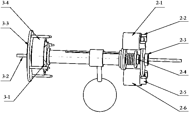
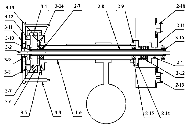
[0029] Such as figure 1 , figure 2 , image 3 , Figure 4 , Figure 5 , Image 6 , Figure 7 , Figure 8 As shown, the variable structure spherical robot capable of overcoming obstacles includes a spherical shell O, a counterweight horizontal offset module I, a rolling motion drive module II, a flywheel drive module III and a flywheel brake module IV; The axis of movement of the module is collinear with the axis of rolling motion of the spherical shell 0; the horizontal displacement module I of the counterweight is located in the left cavity of the spherical shell 0 and is connected with the left wall 0-1 of the spherical shell 0; the rolling The motion driving module II is located in the right cavity of the spherical housing 0 and is connected to the right side wall 0-2 of the spherical housing 0; the flywheel driving module III runs through the left side wall 0-1 of the spherical housing 0 and is connected to the left side wall 0-2 The walls 0-1 are connected; th...

Embodiment 2

[0031] This embodiment is basically the same as Embodiment 1, and the special features are as follows:

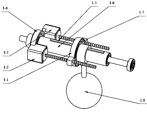
[0032] Such as figure 1 , figure 2 As shown, the above-mentioned counterweight horizontal offset module I includes a counterweight driving arm 1-1, a first servo motor 1-2, a second servo motor 1-3, a first bearing 1-4, and a feather key 1 -5, counterweight shaft 1-6, second bearing 1-7, counterweight 1-8; described counterweight shaft 1-6 is rotationally connected with spherical shell 0 through first bearing 1-4 , so that the counterweight shaft 1-6 and the spherical shell 0 can rotate axially relative to each other but cannot move axially relative to each other; the sliding key 1-5 is horizontally fixed on the counterweight shaft 1-6; the counterweight 1-8 is socketed On the counterweight shaft 1-6 and the feather key 1-5, the mobile pair is formed; the counterweight driving arm 1-1 is hinged to the counterweight 1-8 through the second bearing 1-7, so that the coun...


PUM


Abstract

The invention relates to a variable structure spherical robot capable of crossing an obstacle. The robot comprises a balancing weight horizontal shifting module, a rolling movement driving module, a flywheel driving module and a flywheel braking module. The two basic movement modes of pure rolling and obstacle crossing can be achieved. In the mode of pure rolling, the variable structure spherical robot is similar to a traditional spherical robot driven by center-of-gravity shift, and the variable structure spherical robot has the advantage of being high in movement efficiency. In the mode of obstacle crossing, the variable structure spherical robot can automatically achieve acceleration energy storage for a flywheel set only by increasing driving torque of a power shaft, and when the rotating speed of flywheels reaches the preset threshold value, claw feet hidden on the two sides of a spherical shell can be triggered to be unfolded. Meanwhile, the movement of the spherical shell is blocked, and the flywheels are braked, so that stored energy instantly breaks out and drives the claw feet to rotate to achieve obstacle crossing, and the movement mode of pure rolling is recovered after the energy is completely released. The variable structure spherical robot has the advantages of being compact in structure, easy to control, high in obstacle crossing ability, reliable in system and the like, and the terrain adaptability and practicability of the spherical robot are improved.

Description

technical field [0001] The invention relates to a spherical robot. More specifically, the present invention relates to a structure-changing spherical robot capable of moving over complex terrains and able to overcome obstacles. Background technique [0002] The spherical robot is named for its generally spherical external structure shape, and it is a new type of mobile robot form. Different from traditional wheeled and footed robots, the main characteristic advantage of spherical robots is that the basic movement is realized by rolling the spherical shell, it is easy to realize omnidirectional movement on flat terrain, and it has high movement efficiency and movement speed; movement During the process, when the robot collides or falls from a high place, the closed spherical shell can also effectively protect the internal equipment of the robot. [0003] While the spherical structure has the above-mentioned technical advantages, the application environment of the spherical ...

Claims


Application Information

Patent Timeline
Patent Type & Authority Applications(China)
IPC IPC(8): B62D57/02
Inventor 贾文川王兴兴蒲华燕罗均李龙
Owner SHANGHAI UNIV
Why Eureka
Try Eureka