Narrow-spacing low-SAR high-isolation MIMO antenna

A narrow spacing, high isolation technology, applied in the field of MIMO antennas with low SAR and high isolation, can solve the problem that the antenna isolation cannot meet the requirements, and achieve the effect of reducing the SAR value and improving the isolation.

Inactive Publication Date: 2014-09-03
GUANGDONG UNIV OF TECH
View PDF4 Cites 34 Cited by
  • Summary
  • Abstract
  • Description
  • Claims
  • Application Information

AI Technical Summary

Problems solved by technology

This limits the distance between the antennas can not be placed very ideal, the isolation of the antenna can not meet the requirements

Method used


Image

  • Narrow-spacing low-SAR high-isolation MIMO antenna
  • Narrow-spacing low-SAR high-isolation MIMO antenna
  • Narrow-spacing low-SAR high-isolation MIMO antenna

Examples


Embodiment 1

[0031] The MIMO antenna described in this embodiment is designed for a wireless access terminal with a size of 140mm*72mm, working in the LTE frequency band, and supporting MIMO technology. The wireless access terminal is required to provide voice service and data transmission service at the same time, but working in the same frequency band inevitably brings about mutual interference between two or more antennas for voice and data transmission services.

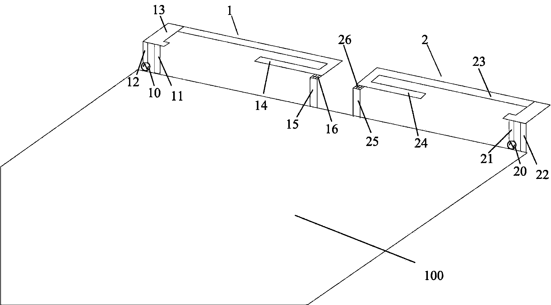
[0032] Such as figure 1 As shown, in this embodiment, two three-dimensional PIFA antennas 1 and 2 are used, and one of the two antennas is a main antenna and the other is a diversity antenna. The main and diversity antennas should be arranged on the two edges of the top of the PCB 100 as much as possible to ensure the largest distance between the two antennas. Preferably, the width of the top of the PCB should be greater than a quarter wavelength. The main and diversity antennas may include several resonances, and each reson...

Embodiment 2

[0042] Such as Figure 4 As shown, the difference between this embodiment and Embodiment 1 is that in Embodiment 1, the feeding points of the two antennas are respectively arranged on the left and right edges of the top of the PCB, in a symmetrical distribution form, while in Embodiment 2, the feeding points are respectively arranged On the left edge and center right of the top of the PCB. The feed points of the main and diversity antennas are set at asymmetrical positions to avoid current resonance positions as much as possible. That is, when the main antenna is activated, the feed point of the diversity antenna is located at the weakest position of the excited floor current; when the diversity antenna is activated, the feed point of the main antenna is also located at the weakest position of the excited floor current.

[0043]The terminal capacitive load technology used in this implementation, in addition to still maintaining the effect of changing the floor current and rad...

Embodiment 3

[0051] Such as Figure 6 As shown, the difference between this embodiment and Embodiment 1 is that the main and diversity antennas of this embodiment increase the high-frequency branches 17 and 27 respectively on the basis of Embodiment 1, which are used to increase the high-frequency band for generating communication, and still maintain the low-frequency The load tuning capacitor on the branch is used to improve the isolation of the low frequency band of the antenna.


PUM


Abstract

The invention discloses a narrow-spacing low-SAR high-isolation MIMO antenna. The narrow-spacing low-SAR high-isolation MIMO antenna comprises a PCB and two antenna bodies used for supporting different service signals, wherein the two antenna bodies are distributed on the two sides of the top end of the PCB and respectively provided with feeding points, the antenna bodies are connected to the PCB through the feeding points respectively, and the feeding points of the two antenna bodies are asymmetrically distributed. According to the antenna, the feeding positions are arranged in the asymmetrical positions on the same side of the PCB, it is avoided that the feeding positions of the antenna are located in the symmetrical current resonance positions, and the isolation degree between the antennas is improved.

Description

technical field [0001] The invention belongs to the technical field of antennas, in particular to a MIMO antenna with narrow spacing, low SAR and high isolation. Background technique [0002] At present, MIMO antenna technology is a major breakthrough in antenna technology in the field of wireless mobile communications. This technology can double the capacity and spectrum utilization of the communication system without increasing the bandwidth, and is a key technology that must be adopted by the new generation of mobile communication systems. MIMO technology allows multiple antennas to transmit or receive multiple spatial streams at the same time, and can distinguish signals sent to or from different spatial orientations. The application of the multi-antenna system enables parallel data streams to be transmitted simultaneously. At the same time, using multiple antennas at the sending end or receiving end can significantly overcome channel fading and reduce the bit error ra...

Claims


Application Information

Patent Timeline
Patent Type & Authority Applications(China)
IPC IPC(8): H01Q1/52H01Q21/00
Inventor 吴艳杰罗文波吴多龙
Owner GUANGDONG UNIV OF TECH
Why Eureka
Try Eureka