
Microwave signal source with narrow linewidth and high signal-to-noise ratio

A technology of microwave signal source and high signal-to-noise ratio, applied in the field of microwave signal source, can solve problems such as system complexity, high noise, and high cost, and achieve the effects of reducing volume, avoiding broadening, and improving quality

Active Publication Date: 2017-10-20
CHANGCHUN UNIV OF SCI & TECH
View PDF6 Cites 0 Cited by
  • Summary
  • Abstract
  • Description
  • Claims
  • Application Information

AI Technical Summary

Problems solved by technology

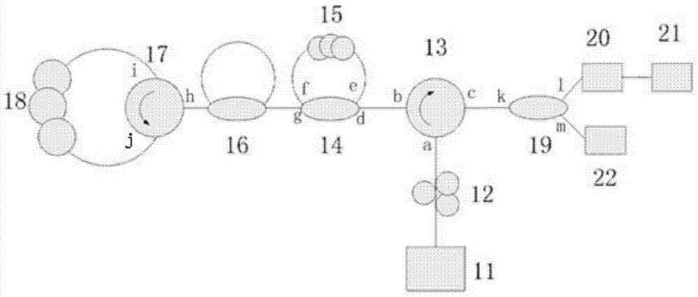
[0007] In order to solve the problems of wide line width, high noise, complex system and high cost in the microwave signal source based on Brillouin laser in the prior art, the present invention proposes a narrow line based on Brillouin frequency shift interval single-frequency fiber laser Microwave signal source with wide bandwidth and high signal-to-noise ratio

Method used


Image

  • Microwave signal source with narrow linewidth and high signal-to-noise ratio
  • Microwave signal source with narrow linewidth and high signal-to-noise ratio
  • Microwave signal source with narrow linewidth and high signal-to-noise ratio

Examples


Embodiment Construction

[0026] The present invention will be described in further detail below in conjunction with the accompanying drawings.

[0027] like figure 2 As shown, the microwave signal source with narrow linewidth and high signal-to-noise ratio includes an ultra-narrow linewidth fiber laser 11, a polarization controller 12, a first circulator 13, a first four-port coupler 14, an ordinary single-mode fiber 15, A second four-port coupler 16 , a second circulator 17 , a polarization-maintaining erbium-doped fiber 18 , a three-port coupler 19 , a photodetector 20 , an electric spectrum analyzer 21 and a spectrum analyzer 22 . The signal source structure can be divided into three parts, that is, the input part, the single-frequency dual-wavelength generation part and the dual-wavelength beat frequency part.

[0028] Input part: ultra-narrow linewidth fiber laser 11, which outputs pump light.

[0029] The pumping light enters the single-frequency dual-wavelength generation part through the po...


PUM


Abstract

A microwave signal source with narrow linewidth and high signal-to-noise ratio belongs to the field of optoelectronics and microwave photonics. In order to solve the problems of wide linewidth and high noise in the prior art, the pump light enters the first A four-port coupler, a part of the pump light enters the ordinary single-mode fiber to excite the first-order Stokes light transmitted in the reverse direction, and the other part of the pump light passes through the first four-port coupler and is composed of the second four-port coupler The microring structure enters the light reflector composed of the second circulator and polarization-maintaining erbium-doped fiber, and returns to the microring structure after passing through the light reflector to enter the Brillouin gain cavity composed of the first four-port coupler and ordinary single-mode fiber , part of the returned pump light enters the ordinary single-mode fiber to excite the next-order Stokes light transmitted in reverse, the other part enters the first circulator and then enters the coupler, and part of the signal light passing through the coupler enters the spectrum analyzer , and the other part enters the photodetector for photoelectric conversion and then enters the spectrum analyzer.

Description

technical field [0001] The invention belongs to the field of optoelectronics and microwave photonics, relates to a microwave signal source with narrow line width and high signal-to-noise ratio, and is applied in the field of wireless communication. Background technique [0002] With the rapid development of mobile communications, the existing wireless spectrum resources can no longer meet the increasing business needs. In order to solve the problem of the shortage of wireless spectrum resources, Radio over Fiber (ROF) has been proposed. Wireless communication over light is a technology that combines light and microwave / millimeter waves. Microwave signals are considered to affect ROF systems because of their low phase noise, ultra-narrow linewidth, high stability, and anti-electromagnetic interference. One of the key technologies of performance. At present, the methods for generating microwaves mainly include the use of fiber Bragg grating pairs, chirped fiber Brig gratings,...

Claims


Application Information

Patent Timeline
Patent Type & Authority Patents(China)
IPC IPC(8): H01S1/02H01S3/067
Inventor 王天枢贾青松张鹏马万卓张靓姜会林
Owner CHANGCHUN UNIV OF SCI & TECH
Learn More