Fillet End Mills

A technology of end mills and rounded corners, which is applied in the direction of milling cutters, forming cutters, milling machine equipment, etc., can solve the problems of variable roughness of the processing surface, high cutting resistance, and inability to increase, etc., to achieve efficient lateral feed processing and rough surface The effect of smoothness and sharpness improvement

Active Publication Date: 2016-05-11
KYOCERA CORP
View PDF6 Cites 0 Cited by
  • Summary
  • Abstract
  • Description
  • Claims
  • Application Information

AI Technical Summary

Problems solved by technology

[0009] However, in the radiused end mills disclosed in Patent Documents 1 and 2, when a deep pocket is provided on the corner R cutting edge, the rake angle at this portion becomes small, and there is a problem that the blade becomes blunt.
In particular, the outer peripheral cutting edge side of the corner R cutting edge is the part that is most prone to wear. However, in the infeed machining, the cutting resistance is high, and the cutting and feeding cannot be increased, so there is a problem that high-efficiency machining cannot be realized.
In addition, the bottom cutting edge is more prone to sliding wear than the outer peripheral cutting edge, and the machined surface of the workpiece may be roughened easily.
Conversely, when the depth of the tool end is excessively reduced, the bottom cutting edge, corner R cutting edge, and peripheral cutting edge cannot be smoothly connected, and a step or corner appears at the joint of the cutting edge, so that there is stuck chip, or Problems such as chipping during cutting

Method used


Image

  • Fillet End Mills
  • Fillet End Mills
  • Fillet End Mills

Examples


Embodiment Construction

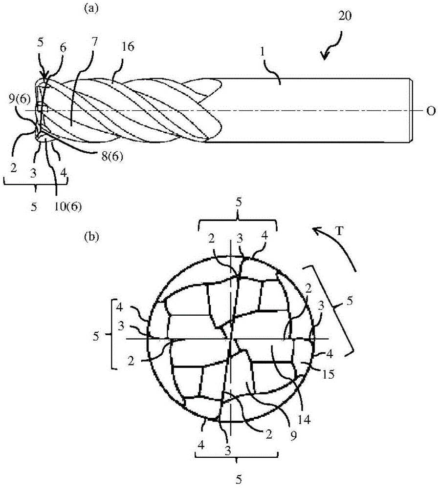
[0024] use figure 1 as well as figure 2 A preferred embodiment example of the radius end mill of the present invention will be described.

[0025] figure 1 , 2 The fillet end mill (hereinafter simply referred to as an end mill) 20 has a substantially cylindrical tool body 1 made of a hard material such as cemented carbide and having a rotational symmetry about a central axis O as a rotation axis. A bottom cutting edge 2 exists on the front end side of the tool body 1 that rotates around the center axis O. As shown in FIG. A peripheral cutting edge 4 exists on the outer periphery of the tool body 1 . A corner R cutting edge 3 connecting the bottom cutting edge 2 and the outer peripheral cutting edge 4 exists between them. Furthermore, the end mill 20 includes a plurality of cutting edges 5 in a series of bottom cutting edge 2 -corner R cutting edge 3 -outer peripheral cutting edge 4 on the front end side.

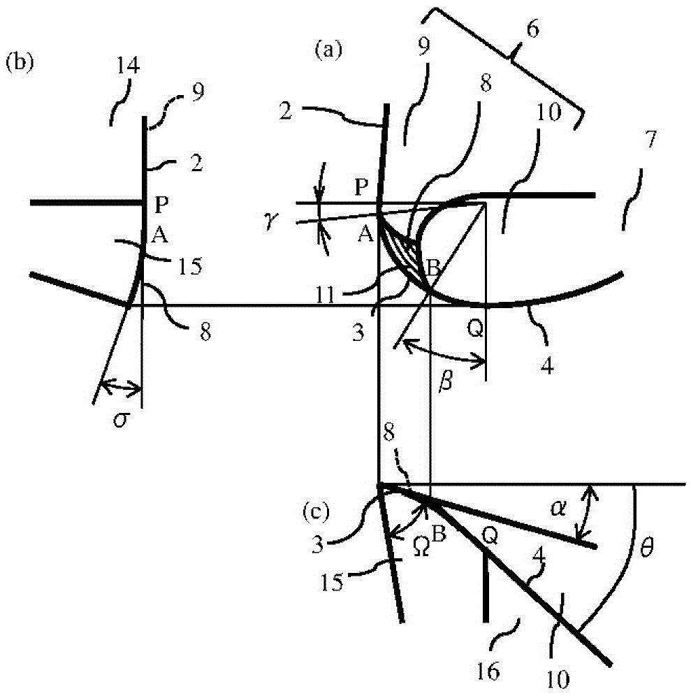
[0026] Further, a rake face 6 is provided continuously to the cu...


PUM


Abstract

[Object] To provide a radius end mill that prevents a stepped or edged portion from being formed on the cutting edge at the connection between the corner R cutting edge and the outer peripheral cutting edge, has a good cutting sharpness, and improves a surface roughness on the machined surface. [Solution] A radius end mill 20 includes a tool body 1 that rotates around a center axis O; a series of a plurality of cutting edges 5 composed of an end cutting edge 2 disposed at a distal end of the tool body 1, an outer peripheral cutting edge 4 disposed on an outer periphery of the tool body 1, and a corner R cutting edge 3 which extends between the end cutting edge 2 and the outer peripheral cutting edge 4; a rake face 6 of the end cutting edge 2, the corner R cutting edge 3 and the outer peripheral cutting edge 4; a chip removal flute 7 which extends at the back of the rake face 6; and a corner gash 8 disposed adjacent to the corner R cutting edge 3 of the rake face 6, wherein the corner gash 8 in a planar shape has an edge, part of which is located at the center portion of the corner R cutting edge 3, and an axial rake 2 at an end portion on the side of the end cutting edge 2 which is in contact with the corner gash 8 on the corner R cutting edge 3 is in the range of 5 to 20 degrees.

Description

technical field [0001] The present invention relates to a radius end mill with a corner R cutting edge. Background technique [0002] Radius end mills are widely used because they can achieve high-efficiency cutting. For example, Patent Document 1 discloses a fillet end mill in which a main end gash is formed at the front end portion of the chip discharge flute intersecting the bottom cutting edge, and an end gash is formed on the main end gash surface. The boundary between the bottom cutting edge and the corner R cutting edge is formed with a sub-cut end deep face across the outer region where the outer peripheral cutting edges intersect. In addition, Patent Document 2 discloses a radius end mill in which a deep cut is provided across the corner R cutting edge from the bottom cutting edge. [0003] prior art literature [0004] patent documents [0005] Patent Document 1: International Publication No. 2004 / 058438 Pamphlet (pamphlet) [0006] Patent Document 2: Japanese...

Claims


Application Information

Patent Timeline
Patent Type & Authority Patents(China)
IPC IPC(8): B23C5/10
CPCB23C5/10B23C2210/045B23C2210/203Y10T407/1948B23C2210/202B23C2210/40B23C2210/48B23C2210/66
Inventor 山寄勉
Owner KYOCERA CORP
Why Eureka
Try Eureka