cutting tool

A cutting tool and cutting edge technology, used in the manufacture of tools, workpieces, drilling tool accessories, etc., can solve the problems that the TiAlN film cannot sufficiently suppress the cutting edge chipping, the tool life cannot be stably extended, and wear, etc., to prevent chipping. , The effect of prolonging tool life and improving wear resistance

Active Publication Date: 2016-10-05
KYOCERA CORP
View PDF6 Cites 0 Cited by
  • Summary
  • Abstract
  • Description
  • Claims
  • Application Information

AI Technical Summary

Problems solved by technology

[0010] However, the TiAlN films described in Patent Document 1 and Patent Document 2 in which the Ti ratio of the cutting edge is increased cannot sufficiently suppress chipping of the cutting edge, and wear may progress rapidly due to the occurrence of chipping.
Therefore, tool life cannot be extended steadily

Method used


Image

  • cutting tool
  • cutting tool
  • cutting tool

Examples


Embodiment 1

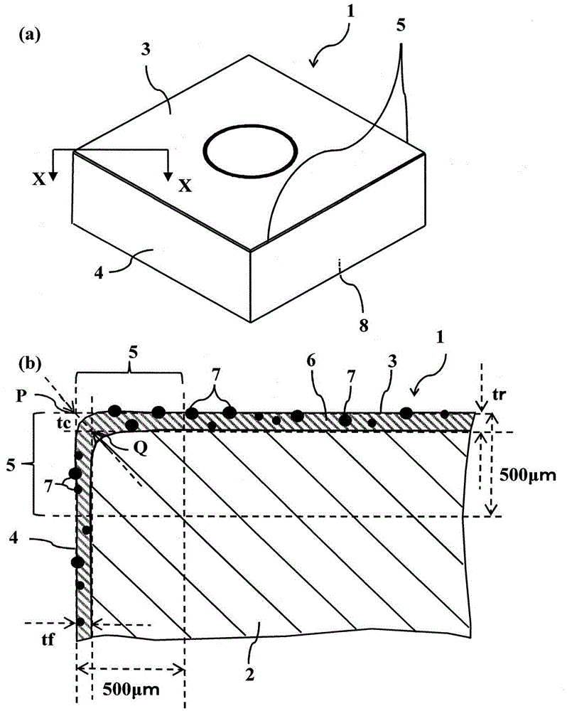
[0050]With tungsten carbide (WC) powder with an average particle size of 0.8 μm as the main component, metal cobalt (Co) powder with an average particle size of 1.2 μm is added at a ratio of 10 mass%, and cobalt (Co) powder with an average particle size of 1.0 μm is added at a ratio of 0.1 mass%. Vanadium carbide (VC) powder, chromium carbide (Cr 3 C 2 ) powder and mixed, and formed into a cutting tool BDMT11T308TR-JT shape (warped edge angle 16°, relief angle 18°) of Kyocera Cutting Tool by extrusion molding. The molded body was placed in a firing furnace, subjected to binder removal treatment, and fired at 1450° C. for 1 hour in a vacuum of 0.01 Pa to produce a cemented carbide. In addition, the rake face surface of each sample was ground by blasting, brushing, or the like. In addition, the produced cemented carbide is subjected to tip processing (honing) by brush grinding.

[0051] For the substrate produced in this way, the center magnets shown in Table 1 were placed on...

Embodiment 2

[0073] In the throwing insert of Sample No. 1 of Example 1, the shape of the throwing insert was changed to Kyocera cutting tools LOMU100408ER-SM (LOMU-SM), BDMT11T308ER-JS (BDMT-JS), SEKW120308TN ( SEKW) and SEKT1203 (SEKT) throw-away blade shapes, and others were prepared in the same manner as in Example 1, and a coating layer was formed. For the obtained sample, evaluation of the coating layer and cutting evaluation were performed in the same manner as in Example 1. The results are shown in Tables 5-8.

[0074] 【table 5】

[0075]

[0076] 【Table 6】

[0077]

[0078] 【Table 7】

[0079]

[0080] 【Table 8】

[0081]

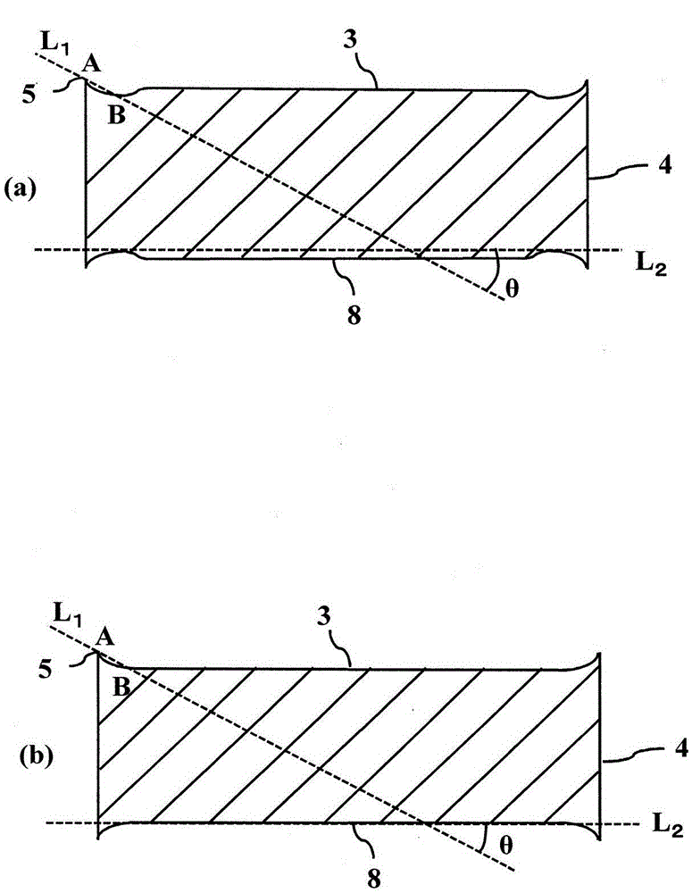
[0082] According to the results shown in Tables 5 to 8, samples No. 10 and 11 with warpage edge angles of 43° and 25° have less welding on the workpiece and wear resistance than sample No. 1. It has good properties and can produce a smooth surface. In addition, samples No. 12 and No. 13, whose warpage edge angles were close to 0°, tended to have ...


PUM


Abstract

The present invention provides a cutting tool excellent in chipping resistance and wear resistance. The cutting tool (1) is coated with CraM1-a (C1-xNx) on the surface of the substrate (2) (wherein, M is selected from Ti, Al, Si, W, Mo, Ta, Hf, Nb, Zr and Y At least one of them, 0.01≤a≤0.4, 0≤x≤1) coating layer (6), and has a cutting edge on the intersecting ridge line of the rake face (3) and flank face (4) (5) The Cr content ratio in the coating layer (6) on the cutting edge (5) side is higher than the Cr content ratio in the coating layer (6) on the flank (4).

Description

technical field [0001] The present invention relates to a cutting tool in which a coating layer is formed on the surface of a substrate. Background technique [0002] Currently, sintered alloys such as cemented carbide and cermets, high-hardness sintered bodies of diamond and cBN (cubic boron nitride), and ceramics such as alumina and silicon nitride are used as substrates for cutting tools. Furthermore, a cutting tool in which a coating layer is formed on the surface of the substrate is used. In these cutting tools, a method of forming a coating layer to improve wear resistance, slidability, or chipping resistance is used. [0003] In addition, physical vapor deposition methods such as ion plating and sputtering are used as a method for forming the coating layer. As for the coating layer, a coating layer containing a nitride mainly composed of Ti and Al has been intensively studied and improved. For these cutting tools, in addition to coating materials, various methods a...

Claims


Application Information

Patent Timeline
Patent Type & Authority Patents(China)
IPC IPC(8): B23B27/14C23C14/06
CPCC23C14/0664C23C28/042C23C28/044C23C28/42C23C14/325Y10T407/24B23B27/14B23B2228/10B23B27/148
Inventor 坂本佳辉
Owner KYOCERA CORP
Why Eureka
Try Eureka