Control circuit of inverter welding machine

A technology for controlling circuits and inverter welding machines, applied in manufacturing tools, welding equipment, arc welding equipment, etc., can solve the problems of welding rods sticking together, threatening personal safety, affecting welding efficiency, etc., and achieves the reduction of welding interruption and reduction Equipment damage and the effect of ensuring welding efficiency

Active Publication Date: 2014-09-10
NINGBO EUROPA WELDING & CUTTING TECH
View PDF7 Cites 4 Cited by
  • Summary
  • Abstract
  • Description
  • Claims
  • Application Information

AI Technical Summary

Problems solved by technology

The inverter welding machine using the control circuit with the above structure has the following disadvantages: When the welder is welding, especially at the moment of arc start, the welding rod is easy to stick to the workpiece, making it impossible to continue welding
This not only interrupts the welding, which affects the welding efficiency, but the short circuit between the two will directly lead to equipment damage or accidents that threaten personal safety.

Method used


Image

  • Control circuit of inverter welding machine
  • Control circuit of inverter welding machine

Examples


Embodiment Construction

[0011] The present invention will be further described below in conjunction with the accompanying drawings and specific embodiments.

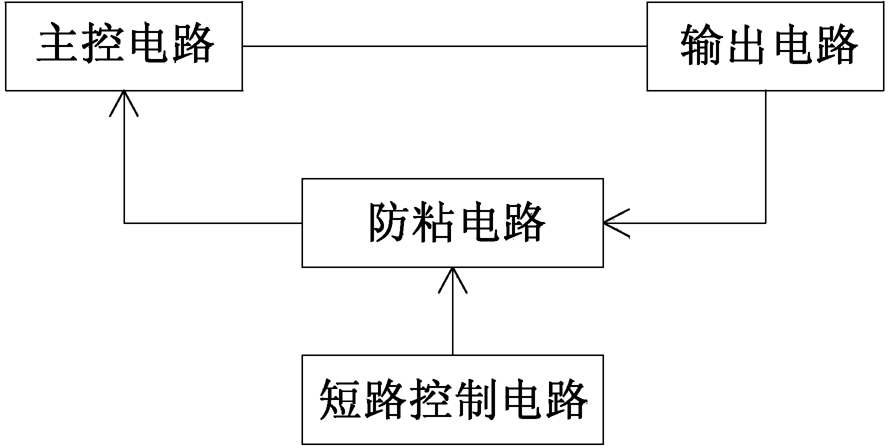
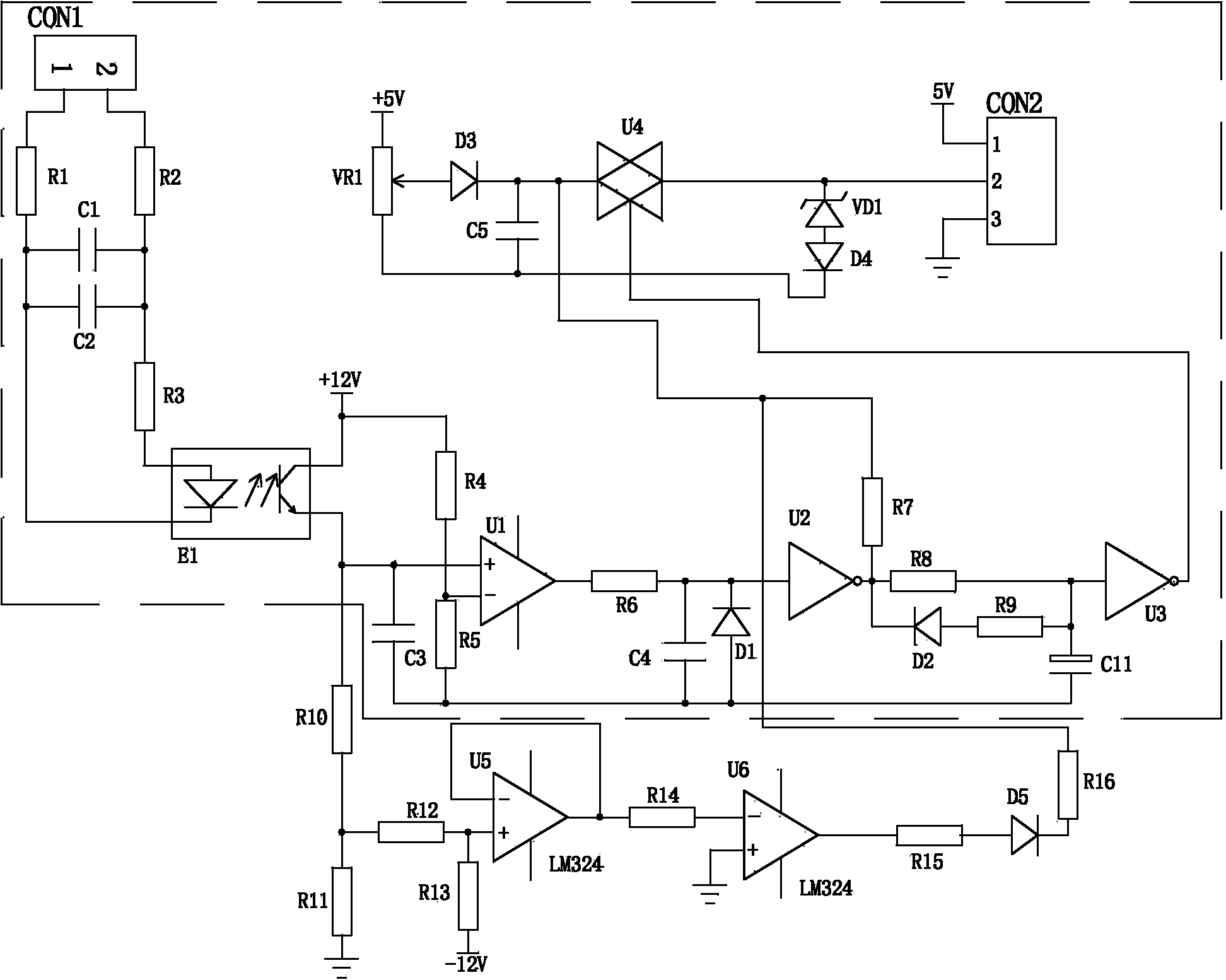
[0012] Such as figure 1 , figure 2 As shown, an inverter welding machine control circuit of the present invention includes a main control circuit and an output circuit, the main control circuit is connected to the output circuit, the above is the prior art; the inverter welding machine control circuit also includes -Anti-adhesive circuit to prevent the welding rod from sticking to the workpiece (e.g. figure 2 The structure in the middle box), the anti-sticking circuit includes resistors R1, R2, R3, R4, R5, R6, R7, R8, R9, capacitors C1, C2, C3, C4, C5, diodes D1, D2, D3 , D4, Zener diode VD1, rheostat VR1, electrolytic capacitor C11, photocoupler E1, comparator U1, inverter U2 and U3, electronic switch U4; one end of the resistor R1 and one end of the resistor R2 are respectively connected to the output circuit The positive and negative po...


PUM


Abstract

The invention discloses a control circuit of an inverter welding machine. The control circuit comprises a master control circuit and an output circuit, and the master control circuit and the output circuit are connected. The control circuit of the inverter welding machine further comprises an adhesion preventing circuit used for preventing adhesion between a welding rod and a workpiece. The control circuit of the inverter welding machine has the advantage that the welding rod can be avoided from being adhered with the workpiece.

Description

technical field [0001] The invention relates to the technical field of electric welding machines, in particular to an inverter welding machine control circuit. Background technique [0002] The control circuit of the inverter welding machine in the prior art includes a main control circuit and an output circuit, and the main control circuit is connected with the output circuit. The inverter welding machine using the control circuit with the above structure has the following disadvantages: when the welder is welding, especially at the moment of starting the arc, the electrode is easily stuck to the workpiece, making it impossible to continue welding. This not only interrupts the welding, thereby affecting the welding efficiency, but the short circuit between the two will directly lead to equipment damage or accidents that threaten personal safety. Contents of the invention [0003] The technical problem to be solved by the present invention is to provide a control circuit ...

Claims


Application Information

Patent Timeline
Patent Type & Authority Applications(China)
IPC IPC(8): B23K9/10B23K9/095
CPCB23K9/10B23K9/1012
Inventor 李抗战
Owner NINGBO EUROPA WELDING & CUTTING TECH
Why Eureka
Try Eureka