Hydraulic joint of underwater manipulator

An underwater manipulator and hydraulic technology, applied in the direction of manipulators, manufacturing tools, joints, etc., can solve the problems of large size and affect the movement of underwater manipulators, and achieve the effect of small internal leakage and good corrosion resistance

Inactive Publication Date: 2014-09-10
TONGJI UNIV
View PDF6 Cites 2 Cited by
  • Summary
  • Abstract
  • Description
  • Claims
  • Application Information

AI Technical Summary

Problems solved by technology

It can maintain the stability of the corner for a long time, and the manufacturing and maintenance costs are very low. However, due to the horizontal arrangement of hydraulic cylinders, the size of the swing cylinder in the lateral direction is large, which will affect the movement of the underwater manipulator.

Method used


Image

  • Hydraulic joint of underwater manipulator

Examples


Embodiment 1

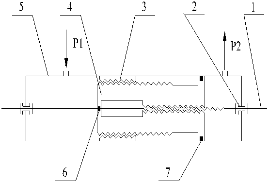
[0018] Embodiment 1: as figure 1 As shown, the device is composed of an output screw 1, a thrust bearing 2, a fixed nut 3, a hollow screw 4, a cylinder 5, a screw sealing ring 6 and a cylinder sealing ring 7. The materials are mostly made of seawater resistant stainless steel. The two ends of the output screw 1 are connected with the cylinder body 5 through the thrust bearing 2 . The fixing nut 3 is assembled with the cylinder body 5 as a whole through thread fastening or interference fit. The hollow screw 4 and the output screw 1 form the first-stage screw pair, and the hollow screw 4 and the fixed nut 3 form the second-stage screw pair. Through the two-stage screw pair, the hydraulic oil pressure at the oil inlet is converted into torque output, and by adjusting the oil pressure difference between the oil inlet and the oil outlet, the forward rotation and reverse rotation of the output screw can be realized, so that Realize large-angle swing motion. Working process of th...


PUM


Abstract

The invention relates to a hydraulic joint of an underwater manipulator, which comprises an output screw, a cylinder body, a cored screw, a fixing nut and thrust bearings, wherein the two ends of the output screw are connected with the cylinder body via the thrust bearings; the fixing nut is assembled with the cylinder body into a whole via threaded fastening or interference fit; the output screw is inserted into a middle hollow part of the cored screw; the cored screw and the output screw form a first stage helical pair; the cored screw and the fixing nut form a second stage helical pair; hydraulic oil pressure at an oil inlet is converted into a torque for output by the two helical pairs; and forward rotation and reverse rotation of the output screw can be achieved by adjusting an oil pressure difference between the oil inlet and an oil outlet, so that large angle pendulum motion is achieved.According to the joint, very small internal leakage can be ensured via a unique helical structure and high precision processing; a stable rotation angle can be kept for a long time without external control; and most of the hydraulic joint is made of seawater corrosion-resisting stainless steel, so that the hydraulic joint is good in corrosion resistance and can operate underwater for a long term.

Description

technical field [0001] The invention relates to a hydraulic joint, in particular to a hydraulic joint of an underwater manipulator. Background technique [0002] There are abundant resources in the ocean, and the speed of human development and utilization of the ocean is gradually accelerating, and the number of ocean projects involved is increasing. At present, in the field of offshore oil and gas exploration and development, most underwater operations have the characteristics of high pressure and heavy load. Driven underwater robots with operational capabilities have been widely used in the field of ocean engineering. The operating capability of the underwater robot is mainly completed by the underwater manipulator mounted on it. Due to the particularity of the working environment, the underwater manipulator is very different from the application on land. The hydraulic joints of the underwater manipulator are required to have high pressure resistance, corrosion resistanc...

Claims


Application Information

Patent Timeline
Patent Type & Authority Applications(China)
IPC IPC(8): B25J17/00
Inventor 卞永明蒋佳李安虎刘广军方晓骏
Owner TONGJI UNIV
Why Eureka
Try Eureka