Module floor slab assembling structure for building and process method

A technology for assembling structures and buildings, applied in building components, building structures, floor slabs, etc., can solve problems such as affecting the quality of residential construction and unable to meet the needs of residential industrialization.

Active Publication Date: 2014-09-10
山东鲁帆集团有限公司
View PDF7 Cites 5 Cited by
  • Summary
  • Abstract
  • Description
  • Claims
  • Application Information

AI Technical Summary

Problems solved by technology

[0006] The technical problem to be solved by the present invention is that the existing housing buildin...

Method used


Image

  • Module floor slab assembling structure for building and process method
  • Module floor slab assembling structure for building and process method
  • Module floor slab assembling structure for building and process method

Examples


Embodiment 1

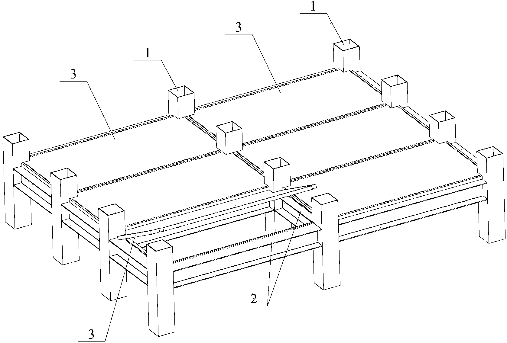
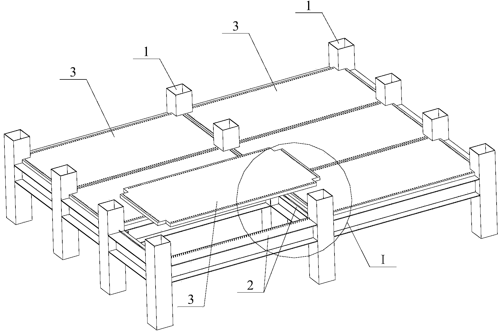
[0036] Such as figure 1 As shown, the main body of the building modular floor assembly structure provided by the embodiment of the present invention includes: steel column 1, steel beam 2 and prefabricated modular floor 3, and the overall design concept adopts the organic combination of assembled steel structure and prefabricated modular floor .

[0037] Among them, four steel building columns 1 form an installation unit of a modular floor 3 , and each installation unit corresponds to a modular floor 3 . It should be understood that figure 1 The six installation units shown in are just examples, and can be selected and set according to actual design and construction needs and specific size requirements. Corresponding to each installation unit, a steel beam 2 for carrying a modular floor 3 is fixedly arranged between two adjacent steel building columns 1 .

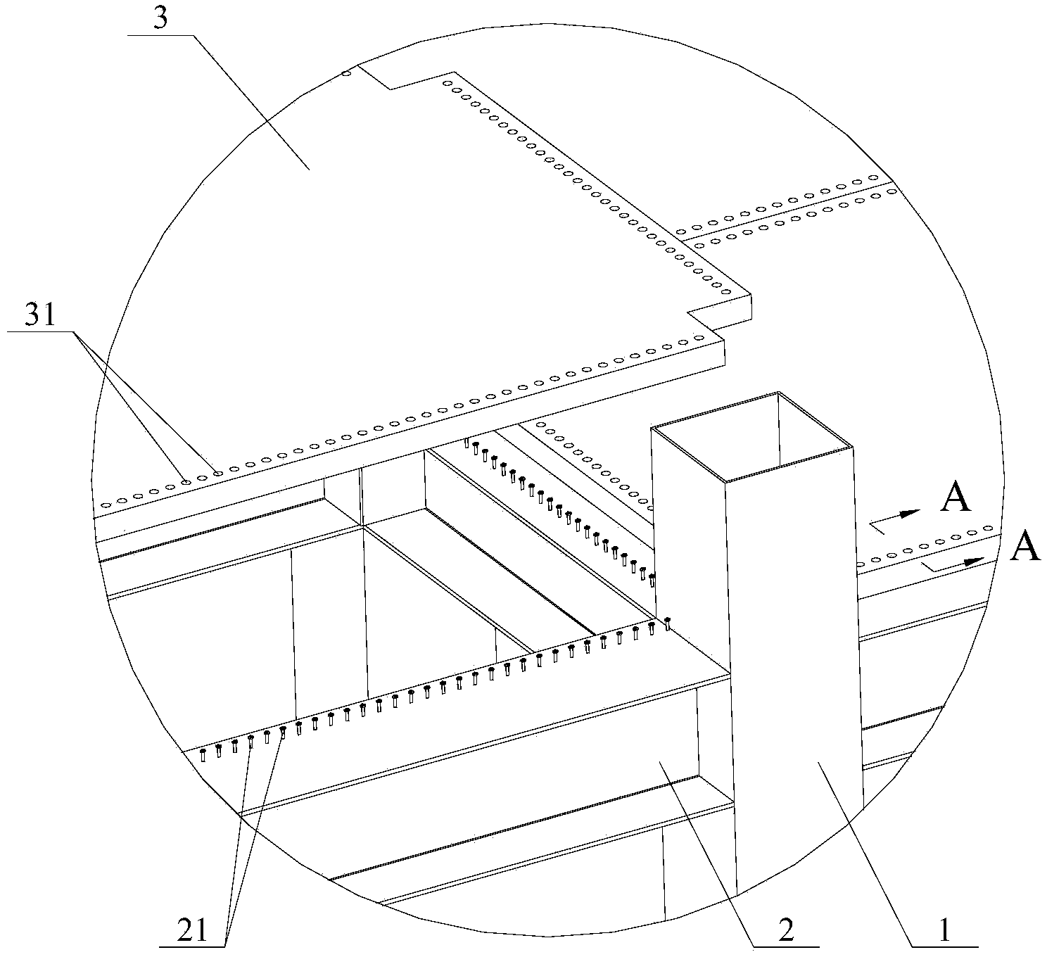
[0038] Wherein, the upper surface of each steel beam 2 is fixedly provided with a vertically extending limit protrusio...

Embodiment 2

[0050] The main structure of the building modular floor assembly structure described in this embodiment is the same as that of Embodiment 1, the difference lies in the connection mode between the steel beam 2 and the steel building column 1 . Such as Figure 7 As shown, the same components are marked with the same symbols to clearly show the differences and connections between the two schemes.

[0051] In this scheme, the steel building column 1 made of square steel is fixedly provided with a stiffener plate 13 in the cavity connected to the steel beam 2; Figure 7 The steel beam 2 on one side and the side wall of the corresponding steel building column 1 are not shown in the figure, so as to clarify the installation position of the rib plate 13. The stiffeners 13 are also two upper and lower intervals, and are roughly flush with the upper and lower surfaces of the steel beam 2 made of I-shaped steel. Fixed connection.

[0052] Similarly, for the steel beam 2 made of I-beam...


PUM


Abstract

The invention relates to the technical field of modular buildings, and provides a floor slab assembling structure for a building and a process method. Steel building posts of the assembling structure form installing units of module floor slabs; steel beams in arrangement corresponding to the installing units are respectively fixed between the two adjacent steel building posts of the installing units; in addition, the upper surface of each steel beam is respectively and fixedly provided with vertically extending position limiting bulges; through holes are correspondingly formed in the edges of the module floor slabs; the edges of the module floor slabs are lapped and butted against the upper surfaces of the steel beams, and in addition, the through holes are sheathed on the position limiting bulges; grouting materials are filled in seams between the position limiting bulges and the through holes and between the module floor slabs; and an integral floor slab is formed after the grouting materials are solidified. Compared with the prior art, the floor slab assembling structure and the process method have the advantages that the factorization degree of main body components in the technical scheme are higher, the assembly can be fast completed in the whole construction technical process, and the conformance to the development trends of the housing industrialization is achieved; and the pre-positioning of the module floor slab installing positions can be realized, the operation intensity of construction personnel can be effectively reduced, and meanwhile, higher integral assembling precision is obtained.

Description

technical field [0001] The invention relates to the technical field of modular buildings, in particular to a building modular floor assembly structure and a process method. Background technique [0002] With the social progress and economic development of our country, more and more energy and environmental issues are concerned by various industries. For residential buildings, the basic shape, material selection, and interior decoration all need to strictly implement environmental protection and energy-saving standards. As we all know, under the circumstances that the contradiction between the construction speed and the growth of housing demand is becoming more and more prominent, a large number of digging and quarrying, borrowing soil and burning bricks to make building materials are becoming more and more serious damage to land resources and the environment; Problems such as design and product standardization have resulted in housing quality not improving significantly wit...

Claims


Application Information

Patent Timeline
IPC IPC(8): E04B5/14
Inventor 张宏亮
Owner 山东鲁帆集团有限公司
Why Eureka
Try Eureka