Fuel injection valve

A fuel injection valve and needle valve technology is applied to direct injection in gasoline cylinders. It can solve the problems of incomplete closing of the injector, affecting the precise injection of the injector, etc., and achieve the effect of increasing the electromagnetic force, improving the ability, and improving the ability of multiple injections.

Active Publication Date: 2014-09-10
CHINA FAW LIMITED WUXI FUEL INJECTIONEQUIP RES INST +1
View PDF8 Cites 8 Cited by
  • Summary
  • Abstract
  • Description
  • Claims
  • Application Information

AI Technical Summary

Problems solved by technology

In addition, when the injector is closed, the needle valve will rebound due to the rapid seating of the ne

Method used


Image

  • Fuel injection valve
  • Fuel injection valve
  • Fuel injection valve

Examples


Example Embodiment

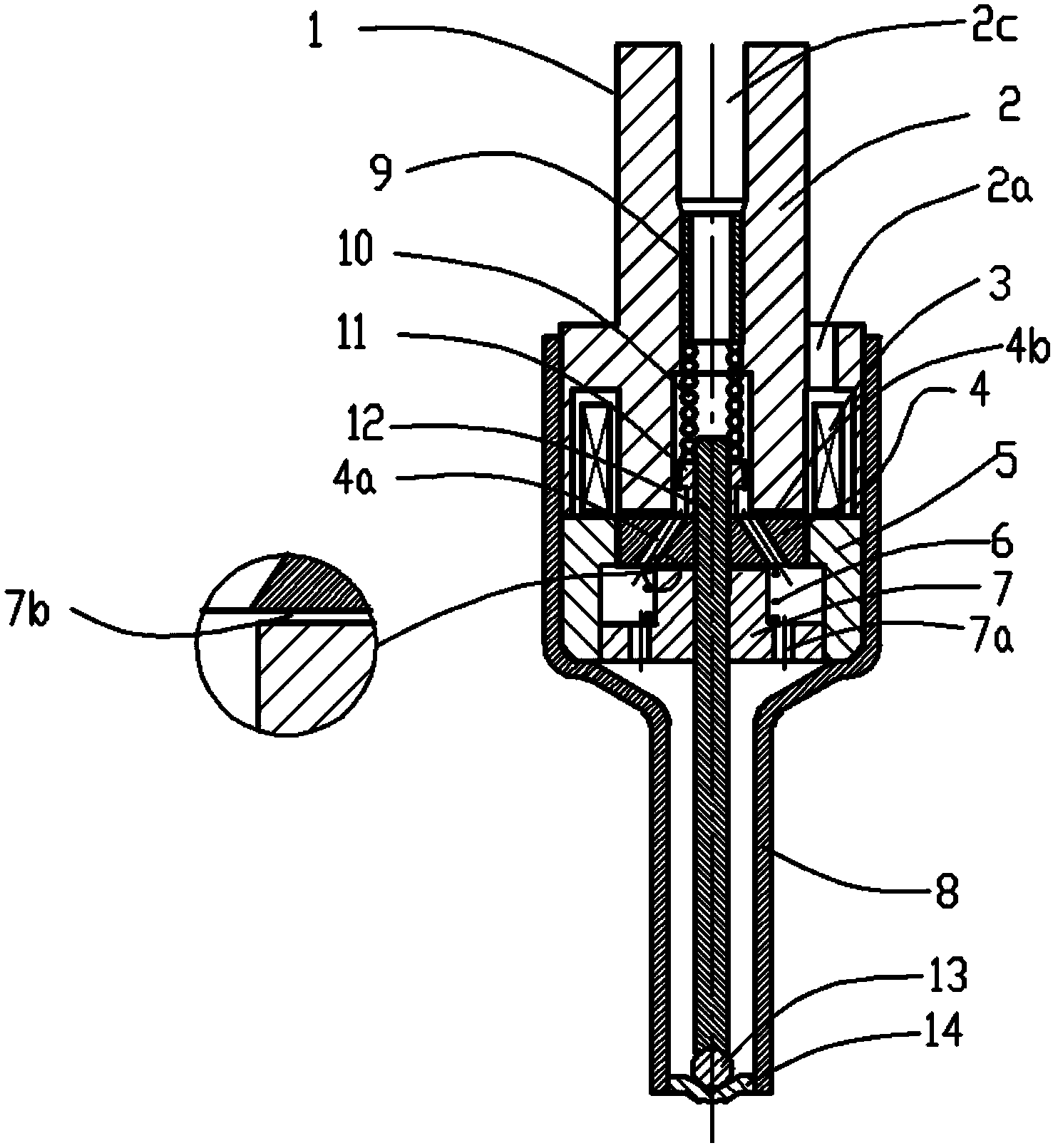
[0025] A fuel injection valve 1 ( figure 1 ):

[0026] Including magnetic core 2, coil 3, armature 4, magnetic ring 5, damping spring 6, damping block 7, outer shell 8, limit core 9, control spring 10, spring seat 11, needle valve 12, sealing ball 13, sealing ball Seat 14.

[0027] Its assembly method:

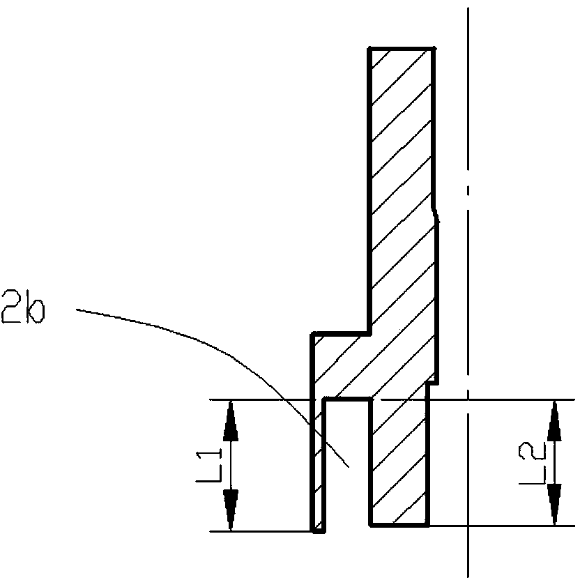
[0028] 1), press the coil 3 assembly (the coil skeleton needs to be fixed) into the coil slot 2b ( figure 2 ), the coil leads are drawn out from hole 2a;

[0029] 2), the coil groove 2b and the coil hole 2a are injected to fix the coil;

[0030] 3) Fix the limit core 9 in the inner cavity of the magnetic core 2 by means of interference;

[0031] 4) Connect the magnetic ring 5 and the magnetic core 2 together by welding at the outer circular joint (concentricity must be ensured);

[0032] 5), the needle valve 12 is welded together with the spring seat 11, and the armature 4 is set on the needle valve;

[0033] 6) Push the armature 4 up until it touches the lower end su...


PUM


Abstract

The invention discloses a fuel injection valve which comprises a magnetic valve, a coil, an armature, a magnetic ring, a damping spring, a damping block, a shell, a limiting core, a control spring, a spring seat, a needle valve, a sealing ball and a sealing ball seat. The coil is arranged in an annular coil groove of the magnetic core, the magnetic ring is fixedly arranged below the magnetic core, the armature is arranged on the upper portion of the inner circle of the magnetic ring and arranged on the lower end face of the magnetic core, the damping block is fixedly arranged below the armature in the inner circle of the magnetic ring, the damping spring is arranged between the armature and the damping block, the needle valve is arranged in the magnetic valve and inserted into the armature and the damping block in a sleeved manner, the upper portion of the needle valve is fixedly connected with the spring seat, and the upper portion of the spring seat is abutted on the limiting core inside the magnetic core while the lower portion of the same is abutted on the armature. By the structure, the fuel injection valve has the advantages of small magnetic flux leakage and high injection response speed, and bouncing when the fuel injection valve is closed can be reduced effectively, and multiple-time injection capability is improved.

Description

technical field [0001] The invention belongs to the technical field of internal combustion engines, and in particular relates to a fuel (gasoline, natural gas, urea, etc.) injection valve, especially for direct injection in gasoline cylinders. Background technique [0002] The existing injection valves used in the field of internal combustion engines are basically controlled by solenoid valves. How to reduce the magnetic flux leakage of solenoid valve coils and improve the working efficiency of solenoid valves is the direction of joint efforts in the industry. In addition, when the fuel injector is closed, the rapid seat of the needle valve will cause the needle valve to rebound, so that the fuel injector is not closed completely, which affects the precise injection of the fuel injector. Contents of the invention [0003] The purpose of the present invention is to provide a fuel injection valve with less flux leakage of the solenoid valve and less bouncing when the fuel in...

Claims


Application Information

Patent Timeline
IPC IPC(8): F02M51/06F02M61/10
Inventor 周望静张武凯卜安珍刘印
Owner CHINA FAW LIMITED WUXI FUEL INJECTIONEQUIP RES INST
Why Eureka
Try Eureka