
Microminiature type angle-of-attack sensor

A sensor, micro-miniature technology, applied in the field of sensors, can solve the problems of difficulty in accurately controlling the friction torque or gap, insufficient sensitivity, and difficulty in miniaturizing the wind vane type angle of attack sensor, and achieves a clean aerodynamic shape, compact structure, and elimination of influences. Effect

Active Publication Date: 2014-09-10
COMAC +1
View PDF5 Cites 10 Cited by
  • Summary
  • Abstract
  • Description
  • Claims
  • Application Information

AI Technical Summary

Problems solved by technology

[0003] In traditional designs, due to factors such as structural maintenance and the volume of the angle measuring device, it is often difficult to miniaturize the windvane angle of attack sensor; the aerodynamic shape of the windvane includes the influence of joints and fasteners connected to the windvane shaft Parts with a clean aerodynamic shape are unfavorable for buildings that need to accurately capture the characteristics of the flow field, so it is difficult to use them in wind tunnel experiments with smaller scale models; traditional angle measurement devices include potentiometers and mechanicals. The device has a frictional moment or gap that is difficult to accurately control, which is very detrimental to the accuracy of the angle of attack measurement, and the wear caused by long-term use will seriously affect the reliability and accuracy of the angle of attack sensor; Although the processing method is relatively simple, its sensitivity is insufficient under the condition of low dynamic pressure flow

Method used


Image

  • Microminiature type angle-of-attack sensor
  • Microminiature type angle-of-attack sensor
  • Microminiature type angle-of-attack sensor

Examples


Embodiment Construction

[0033] As required, specific embodiments of the invention will be disclosed herein. However, it should be understood that the embodiments disclosed herein are merely typical examples of the invention, which can be embodied in various forms. Therefore, specific details disclosed herein are not to be considered limiting, but merely as a basis for the claims and as a representative basis for teaching one skilled in the art to variously employ the invention in any appropriate way in practice, This includes taking various features disclosed herein and combining features that may not be expressly disclosed herein.

[0034] It should be noted that herein, directional representations, such as top surface, bottom surface, top, bottom, etc., used to explain the structure and action of various parts of the disclosed embodiments are not absolute but relative. These representations are appropriate when various parts of the disclosed embodiments are located in the locations shown in the fi...


PUM


Abstract

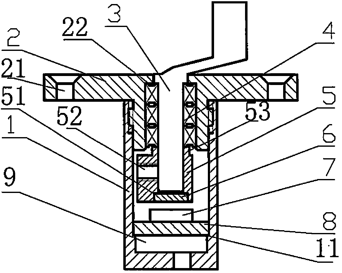
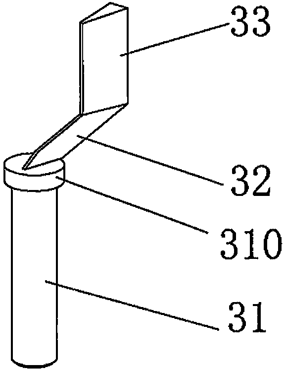
The invention provides a microminiature type angle-of-attack sensor. The microminiature type angle-of-attack sensor comprises an installing seat, an integrated force-arm type weather vane, a bearing, a balancing weight and an angle-of-attack acquiring device, wherein the installing seat is provided with an internal containing space; the integrated force-arm type weather vane comprises a weather-vane shaft, a weather-vane force arm extending obliquely from one end of the weather-vane shaft, and a weather-vane wing surface supported by the weather-vane force arm; the weather-vane force arm and the weather-vane wing surface are exposed at the outer part of the installing seat and rotate along with airflow to drive the weather-vane shaft to rotate together; the bearing is arranged in the internal containing space and is used for supporting the weather-vane shaft penetrating through the bearing; the balancing weight is arranged at the other end of the weather-vane shaft and is positioned under the bearing in the internal containing space; and the angle-of-attack acquiring device is arranged at the bottom part of the internal containing space and is connected with the weather-vane shaft. The microminiature type angle-of-attack sensor provided by the invention has the advantages of compact structure, clean pneumatic appearance, small interference for a flow field, easiness in miniaturization, low friction force and high measuring accuracy.

Description

technical field [0001] The present invention relates to the technical field of sensors, and more particularly relates to a micro-miniature angle-of-attack sensor, which is used to measure the local airflow direction on the surface of a model in a wind tunnel experiment, or used for atmospheric data collection of an unmanned aerial vehicle. Background technique [0002] The angle of attack sensor, also known as the angle of attack sensor, is usually installed on the side of the aircraft fuselage to measure the flight angle of attack. The existing angle-of-attack sensors are mainly divided into two categories: differential pressure zero-type angle-of-attack sensors and windvane-type angle-of-attack sensors. Due to the complex structure and high assembly precision requirements of the pressure difference zero-type angle-of-attack sensor, it is basically replaced by the wind vane-type angle-of-attack sensor. The windvane angle-of-attack sensor mainly includes components such as ...

Claims


Application Information

Patent Timeline
IPC IPC(8): G01C1/00G01M9/06
CPCG01M9/065G01P13/025
Inventor 吴大卫宋磊杨士普刘凯礼谭兆光孙一峰钱光平蒋晓莉周星
Owner COMAC
Learn More