
Computing method of digital sun sensor centroid based on detecting window

A sun sensor and detection window technology, applied in navigation calculation tools, instruments, measuring devices, etc., can solve problems such as slow calculation speed, poor real-time performance, and slow data update rate, reduce threshold requirements, improve real-time performance, and improve The effect of precision

Inactive Publication Date: 2014-09-10
CHANGCHUN INST OF OPTICS FINE MECHANICS & PHYSICS CHINESE ACAD OF SCI
View PDF3 Cites 5 Cited by
  • Summary
  • Abstract
  • Description
  • Claims
  • Application Information

AI Technical Summary

Problems solved by technology

[0006] In order to solve the problems of slow calculation speed, slow data update rate and poor real-time performance in existing calculation methods, the present invention provides a detection window-based digital sun sensor centroid calculation method

Method used


Image

  • Computing method of digital sun sensor centroid based on detecting window
  • Computing method of digital sun sensor centroid based on detecting window
  • Computing method of digital sun sensor centroid based on detecting window

Examples


specific Embodiment approach 1

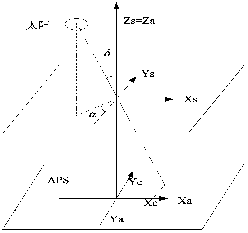
[0030] Specific implementation mode one, combination Figure 1 to Figure 3 In this embodiment, the method for calculating the centroid of the digital sun sensor based on the detection window will be described in combination with figure 1 , OXsYsZs is the reference coordinate system of the solar sensor, the imaging aperture is located at the O point coordinate, and the Zs axis is perpendicular to the photosensitive surface of the detector. xC and YC are the coordinates of the center of gravity of the light spot, and α and δ are the azimuth and elevation angles of the sun in the reference coordinate system. The method is implemented by the following steps:

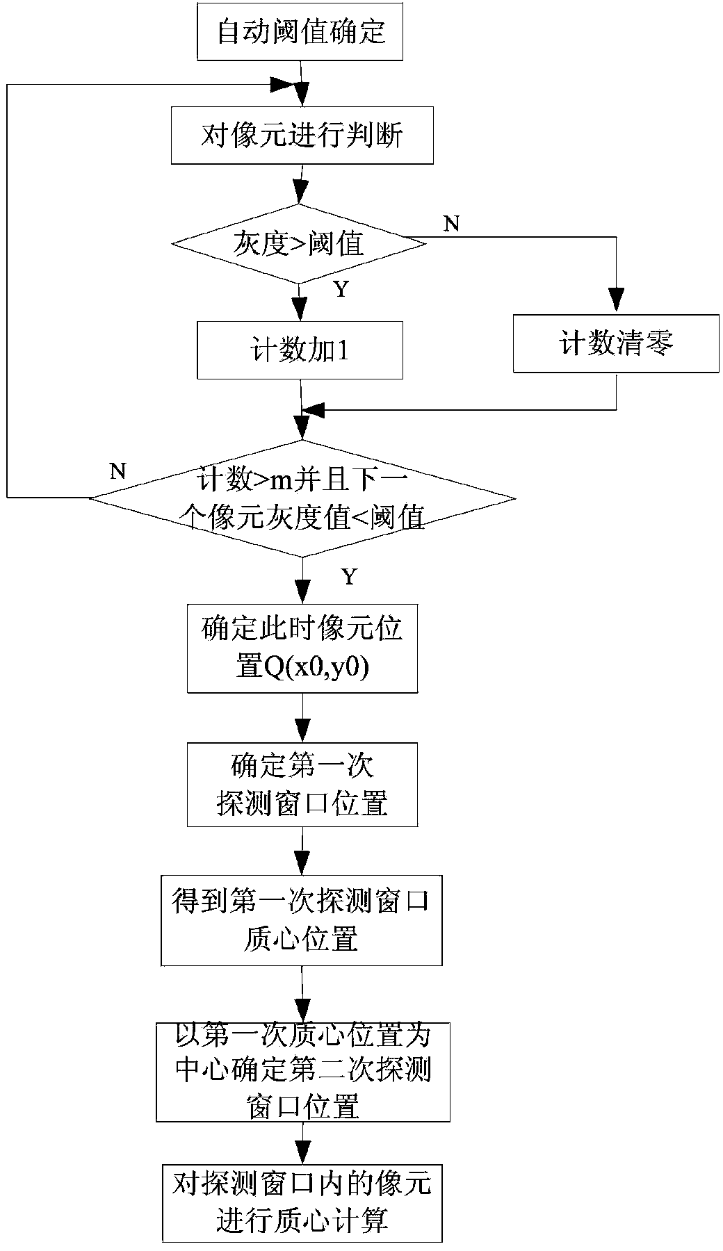
[0031] Step 1: Determine the adaptive threshold;

[0032] The image output by the image sensor is collected, and the gray value of the pixel is judged at the same time. Because the digital sun sensor has only one small hole to transmit light, the rest of the background should be kept as opaque as possible, so the image with gray...

specific Embodiment approach 2

[0054] Embodiment 2 This embodiment is an embodiment of the method for calculating the centroid of a digital sun sensor based on a detection window described in Embodiment 1:

[0055] Step 1: Automatic threshold determination;

[0056] The pixels whose gray value is greater than 0 are summed and averaged as the threshold of the next frame image:

[0057] T = X i = 1 n p i n ( p i > 0 )

[0058] Among them, T is the threshold; p i Is the gray value of a certain pixel; n is the number of pixels whose gray value is greater than 0.

[0059] Step 2: Determine the size of the first detection window;

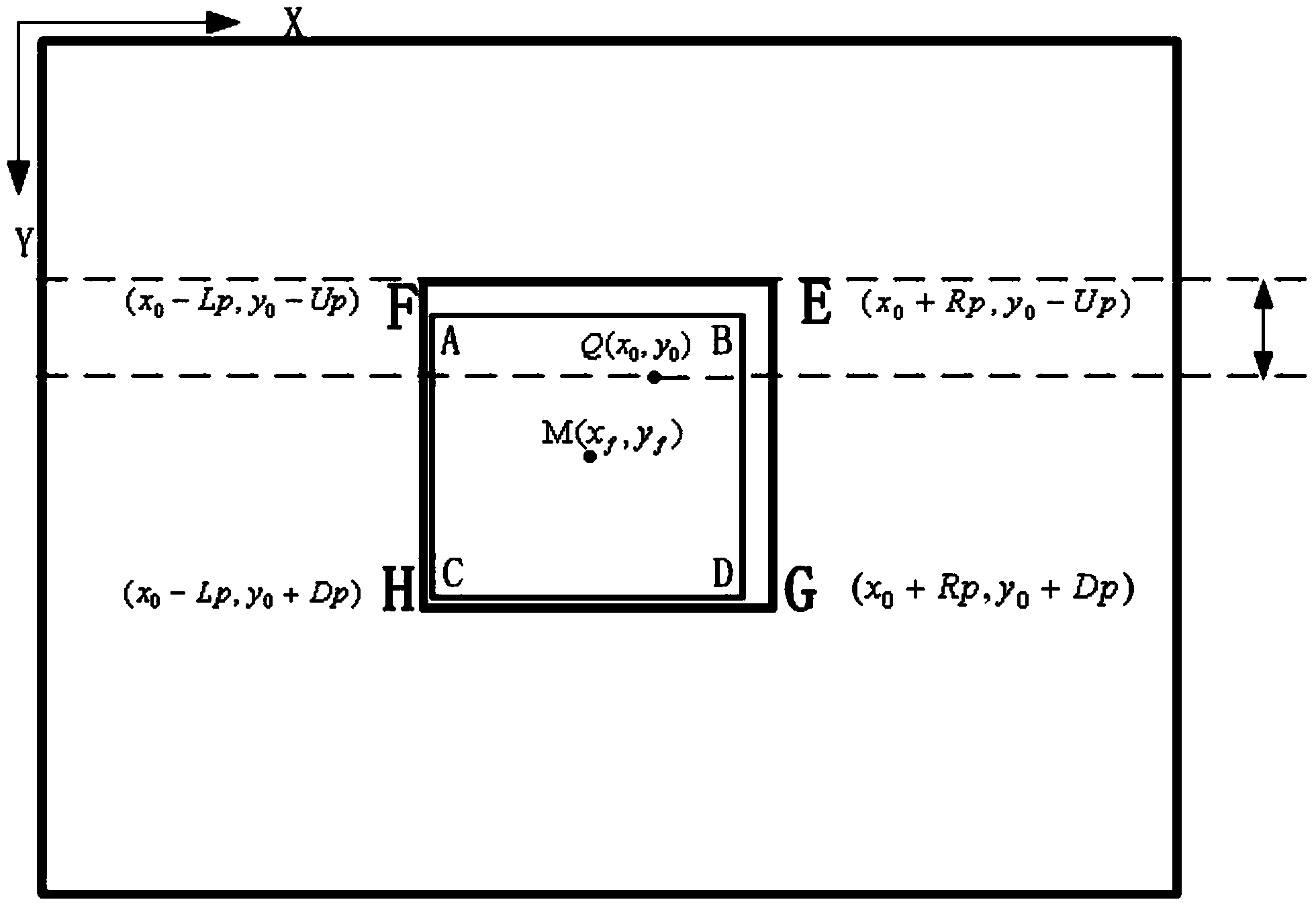
[0060] The detection window size is required to include the entire light spot. Assuming that the sensor aperture is square, the side length is 10 pixels, and the aperture height is 4mm, considering the diffraction problem, the first detection window size is selected as 20 pixels×20 pixels ;

[0061] Step 3: Determine the position of the first dete...


PUM


Abstract

The invention discloses a computing method of a digital sun sensor centroid based on a detecting window, relates to the field of optical posture sensors, and solves the problems that the computing speed is slow, the data updating rate is slow, and the instantaneity is poor in the existing computing method. The computing method provided by the invention comprising the following steps of determining a self-adaption threshold value and a position of a first-time detecting window, optimizing the first-time detecting window, and determining the position of a second-time detecting window; and realizing the facula centroid computation on a picture element in the second-time detecting window. The computing method adopts a threshold value and the detecting window to match, the centroid computation on the picture element in the detecting window is realized, the computation of an automatic threshold value is simplified, the centroid computation precision is improved, and the method provides the basis for posture positioning of the sun sensor.

Description

Technical field [0001] The invention relates to the field of optical attitude sensors, in particular to a method for calculating the centroid of a digital sun sensor based on a detection window. Background technique [0002] The digital sun sensor mainly determines the position of the sun in the coordinate system of the sensor body by detecting the vector position of the sun, and then obtains the position of the sun in the satellite body coordinate system through coordinate matrix transformation. The principle of the attitude measurement of the sun sensor is as follows figure 1 Shown. The orientation of the sun vector is determined by the position of the sun's spot on the sensor and the aperture height of the sun sensor. Therefore, determining the position of the sun's spot is the basis for realizing the attitude positioning of the digital sun sensor. [0003] The traditional method of calculating the centroid of the digital sun sensor is to first determine the image threshold, se...

Claims


Application Information

Patent Timeline
Patent Type & Authority Applications(China)
IPC IPC(8): G01C25/00
CPCG01C21/20
Inventor 郑晓云王天聪张贵祥徐伟钟兴金光
Owner CHANGCHUN INST OF OPTICS FINE MECHANICS & PHYSICS CHINESE ACAD OF SCI
Learn More