Mechanical device for multi-angle milling force loading of high-speed spindle unit

A high-speed spindle and mechanical device technology, applied in measuring devices, testing of mechanical components, testing of machine/structural components, etc., can solve problems such as inaccurate measurement of loading force, and achieve the effect of solving inaccurate measurement.

Active Publication Date: 2016-06-08
通用技术集团沈阳机床有限责任公司
View PDF9 Cites 0 Cited by
  • Summary
  • Abstract
  • Description
  • Claims
  • Application Information

AI Technical Summary

Problems solved by technology

[0004] In order to solve the problems existing in the prior art, the invention discloses a mechanical device for multi-angle milling force loading of a high-speed spindle unit. The device is equipped with a spindle unit, a force transmission mechanism and a force loading mechanism. It solves the problem of inaccurate measurement of the loading force when the radial and axial loads have a resultant force direction at the same time, and avoids the different effects of different rigidity of the force loading mechanism on the test results.

Method used


Image

  • Mechanical device for multi-angle milling force loading of high-speed spindle unit
  • Mechanical device for multi-angle milling force loading of high-speed spindle unit
  • Mechanical device for multi-angle milling force loading of high-speed spindle unit

Examples


Embodiment Construction

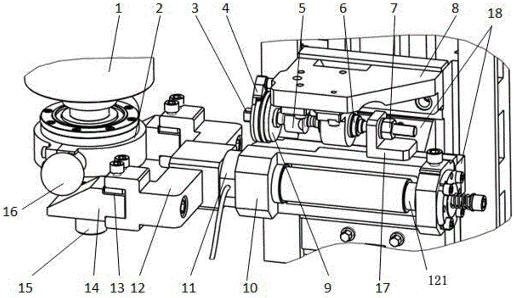
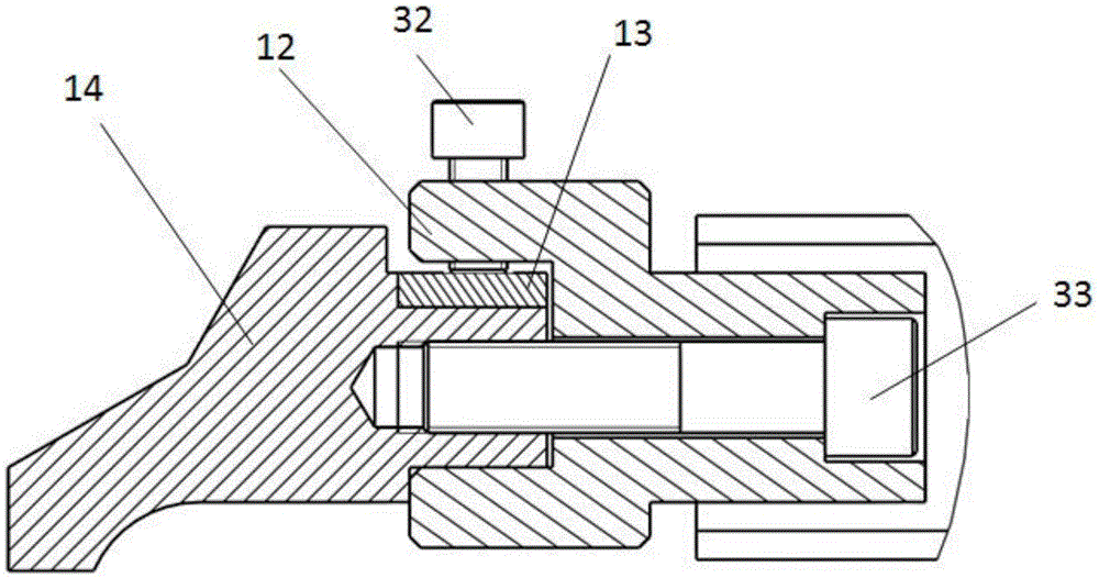
[0030] like Figure 1-5 As shown, the mechanical device for multi-angle milling force loading of the high-speed spindle unit includes the cutter shaft 15 connected with the spindle unit 1, the bearing seat 2 arranged on the cutter shaft 15, and the afterburner fixed on both sides of the bearing seat 2 Ball 16, force transmission mechanism and force loading mechanism. like figure 1As shown, the spindle unit 1 is fixed on the test bench, one end of the spindle unit 1 is connected with a cutter shaft 15, the cutter shaft 15 is provided with a bearing seat 2, and the two ends of the bearing seat 2 are fixed with an afterburner ball 16; The transmission mechanism includes a booster base 10 arranged on the linear guide rail-slider 18 and having a coaxial hole, a U-shaped frame 12 arranged at the head end of the booster base 10 and a booster slope 14 arranged at the head end of the U-shaped frame 12, The mandrel 121 at the tail end of the U-shaped frame 12 cooperates with the coaxi...


PUM


Abstract

The invention discloses a mechanical device for multi-angle milling force loading of a high-speed spindle unit, which includes: a cutter shaft connected to the spindle unit, a bearing seat arranged on the cutter shaft, and force balls fixed on both sides of the bearing seat. The force transmission mechanism and the force loading mechanism, the force transmission mechanism, including the force-exerting seat arranged on the linear guide rail-slider and having a coaxial hole, the U-shaped frame arranged at one end of the force-enforced seat and the added force seat arranged at one end of the U-shaped frame The force ramp, the mandrel of the U-shaped frame is matched with the coaxial hole of the booster base, and the booster ball is placed on the booster ramp; the force loading mechanism is connected with the booster base, including the differential screw micro-feed mechanism and / or Cylinder loading mechanism. The device economically and feasiblely solves the test of the cutting force of the spindle test, and can simulate various working conditions of the spindle unit, so as to save time, labor, energy and high efficiency.

Description

technical field [0001] The invention relates to the field of cutting force simulation tests, in particular to a mechanical device for loading high-speed spindle units with multi-angle milling forces. Background technique [0002] The spindle unit is the key functional part of the CNC machine tool, which has an important influence on the machining performance of the machine tool. The load of the main shaft refers to the force and moment that occurs during the working process; the load test of the main shaft unit is an important means to control product quality and verify product performance. From the perspective of the spindle itself, the moment load test is more closely related to the performance of the spindle motor, while the loading of the cutting force focuses on the consideration of the spindle support structure and support bearing performance. During the test or test, the force and moment of simulated loading are usually realized separately. [0003] The current cutt...

Claims


Application Information

Patent Timeline
Patent Type & Authority Patents(China)
IPC IPC(8): G01M13/00
Inventor 李宇鹏林剑峰李焱马晓波刘阔谭智孔祥志高秀峰杨祥东关晓勇
Owner 通用技术集团沈阳机床有限责任公司
Why Eureka
Try Eureka