motor control device
A technology of motor control and current vector, applied in the direction of motor generator control, AC motor control, control of electromechanical transmission devices, etc., can solve the problems of no reflection, reduced effect of pulsating torque suppression, etc., and achieve the effect of suppressing pulsating torque
- Summary
- Abstract
- Description
- Claims
- Application Information
AI Technical Summary
Problems solved by technology
Method used
Image
Examples
no. 1 Embodiment approach 》
[0034]
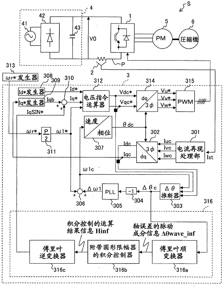
[0035] figure 1 It is a configuration diagram of the motor control device according to the present embodiment. figure 1 The motor control system S shown is a system for driving a compressor 6 (for example, a rotary compressor) by controlling the output voltage of the inverter 1 to rotate the rotor (not shown) of the AC motor 5 . The motor control system S includes an inverter 1 , a current sensor 2 , and a motor control device 3 .
[0036] The inverter 1 is a power converter that converts the DC voltage V0 input from the DC power supply 4 into a three-phase AC voltage, and outputs it to the AC motor 5 . Here, the DC power supply 4 is a device that converts AC power input from the AC power supply 41 into DC power using a rectifier circuit 42 and a smoothing capacitor 43 .
[0037] The inverter 1 has a plurality of switching elements (not shown), and converts the DC voltage V0 into a three-phase AC voltage by switching ON / OFF of the switching elements according to t...
no. 2 Embodiment approach
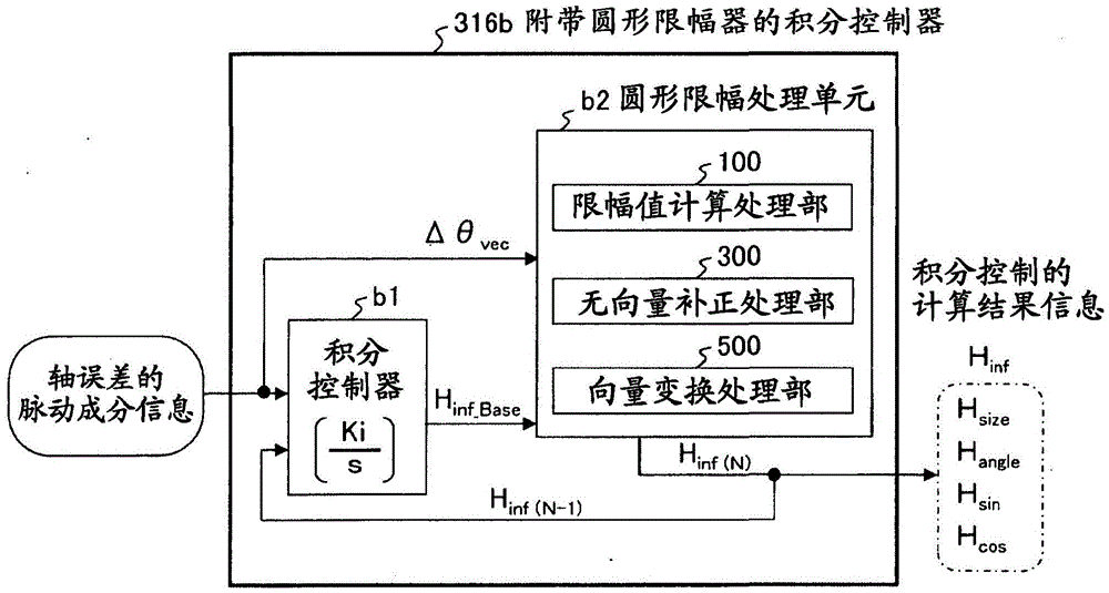
[0117] The circular clipping processing unit b2 of the motor control device 3 of the second embodiment (refer to image 3 ) equipped with no vector value correction processing unit 300A (refer to image 3) is different from the first embodiment, and the others are the same as the first embodiment. Therefore, the different parts will be described, and the description of the parts overlapping with the first embodiment will be omitted.
[0118] (without vector value correction processing unit)
[0119] Figure 10 It is a configuration diagram of a non-vector correction processing unit included in the circular clipping processing unit of the motor control device according to the present embodiment.
[0120] In this embodiment, the circular clipping processing unit b2 is characterized in that no variation tolerance range (equivalent to the rectangular range A described in the first embodiment: refer to Figure 9 ) performs circular clipping processing.
[0121] like Figure 1...
PUM
 Abstract
Description
Claims
Application Information
 - R&D
- Intellectual Property
- Life Sciences
- Materials
- Tech Scout
- Unparalleled Data Quality
- Higher Quality Content
- 60% Fewer Hallucinations
Browse by: Latest US Patents, China's latest patents, Technical Efficacy Thesaurus, Application Domain, Technology Topic, Popular Technical Reports.
© 2025 PatSnap. All rights reserved.Legal|Privacy policy|Modern Slavery Act Transparency Statement|Sitemap|About US| Contact US: help@patsnap.com


