Stamping automatic feeding device and method

A technology of automatic feeding and punching machine, applied in the direction of feeding device, positioning device, storage device, etc., can solve the problems of high labor intensity, low production efficiency, difficult positioning of materials, saving time for returning to the position, uninterrupted The effect of continuous automatic feeding

Active Publication Date: 2014-09-17
宜昌市综艺包装有限公司
View PDF9 Cites 28 Cited by
  • Summary
  • Abstract
  • Description
  • Claims
  • Application Information

AI Technical Summary

Problems solved by technology

[0002] The old-fashioned stamping machines in the prior art mostly use manual feeding, such as punching thin plate parts to form the parts of the wine packaging box cover, which has low production efficiency, high labor intensity and high risk
However, the special CNC equipment has complex structure and high cost.
[0003] For example, Chinese patent application 201310249323.X discloses an automatic feeding device for a stamping machine tool, which uses a manipulator to cooperate with a pushing mechanism to realize feeding, and the structure is relatively complicated.
Another example is the Chinese patent 201010148918.2 which discloses an automatic feeder for a punch press, which has a complex feeding drive device, and its feeding is realized by moving the thin plate above the pile. In actual use, due to the deformation of the thin plate parts, the shifting Material positioning is very difficult

Method used


Image

  • Stamping automatic feeding device and method
  • Stamping automatic feeding device and method
  • Stamping automatic feeding device and method

Examples


Embodiment 1

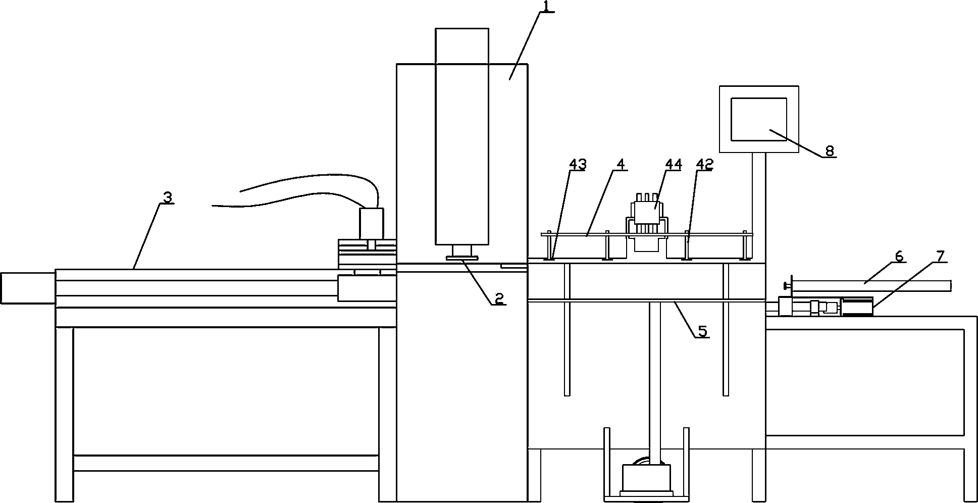
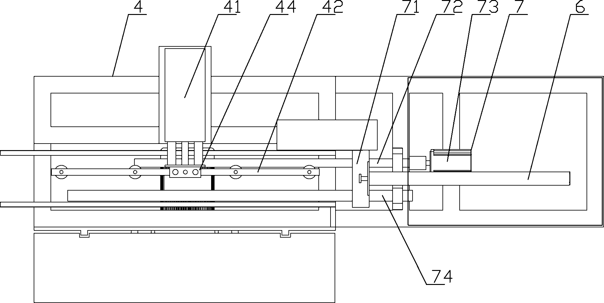
[0030] like Figure 1-5 Among them, a stamping automatic feeding device, including a pusher mechanism located on one side of the punching machine 1, the structure of the pusher mechanism is that the pusher plate 71 is fixedly installed on the piston rod of the pusher cylinder 6, and the pusher cylinder 6. Fixedly installed on the nut seat of the pusher ball screw 72, the nut seat of the pusher ball screw 72 is also slidably installed on the pusher guide rail 74, and the lead screw of the pusher ball screw 72 is connected with the pusher servo motor 73 , Pushing material servo motor 73 is fixedly installed on the frame, and the two ends of pushing material ball screw 72 and pushing material guide rail 74 are installed on the frame by supporting seat.

[0031] When in use, the plate-shaped material is placed on the material guide frame 9, and the piston rod of the material pushing cylinder 6 is stretched out to push the material to the initial processing position. The length of...

Embodiment 2

[0045] A method for realizing automatic feeding by using the above-mentioned stamping automatic feeding device, comprising the following steps:

[0046] First push the material to the initial processing position with the material pushing cylinder 6, and then the material pushing servo motor 73 drives the material pushing plate 71 to push the material one processing station at a time, thereby realizing the automatic feeding of the material.

[0047] Optimally, the material on one side of the pushing cylinder 6 is transported to the pushing plate 71 and the material guide frame 9 by the feeding mechanism 4;

[0048] The steps are: the piston rod of the horizontal feeding cylinder 41 is stretched out, and when it is in place, the piston rod of the vertical feeding cylinder 44 is stretched out, the feeding rack 42 falls to the top of the material, the vacuum suction cup 43 sucks the material, and the vertical feeding cylinder 44 The piston rod is retracted, and the piston rod of t...

Embodiment 3

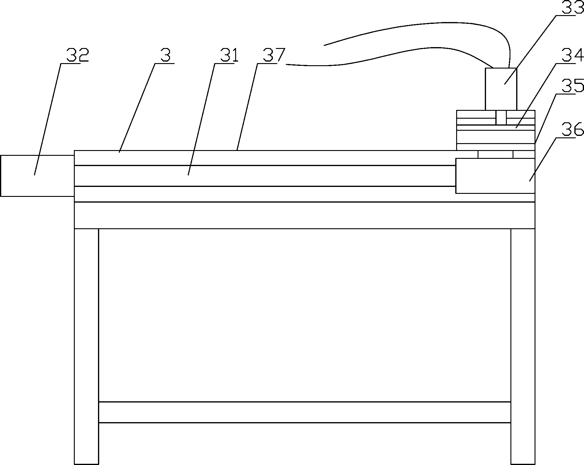
[0054] like figure 1 Among them, firstly, the feeding mechanism 4 sends the material to the pushing position through the vacuum suction cup, and the pushing cylinder quickly resets and takes the material and stops at the waiting position for feeding. Then the material is pushed to the left by the material pushing cylinder 6 of the material pushing mechanism to the material pushing servo ready position, and then the material is precisely positioned to the first processing position by the material pushing servo motor 73 through the material pushing ball screw 72, and punched by a punching machine , and then positioned to the second processing position by the pusher servo motor 73, when pushed to the fourth processing position, the material pulling mechanism 3 works, the material pulling cylinder 33 of the material pulling mechanism acts, and the pressure plate 34 clamps the upper left side of the material corner, and under the action of the pulling servo motor 32, accurately loc...


PUM


Abstract

The invention discloses a stamping automatic feeding device and a stamping automatic feeding method. The device comprises a pushing mechanism which is located on one side of a punching machine, wherein the structure of the pushing mechanism is that a pushing plate is fixedly mounted on a piston rod of a pushing air cylinder; the pushing air cylinder is fixedly mounted on a nut seat of a pushing ball screw; the nut seat of the pushing ball screw is mounted on a pushing guide rail in a sliding way; a screw of the pushing ball screw is connected with a pushing servo motor; the pushing servo motor is fixedly mounted on a rack; two ends of the pushing ball screw and the pushing guide rail are mounted on the rack by bearing seats. Firstly, materials are pushed to an initial processing position by the pushing air cylinder, and then the pushing servo motor drives the pushing plate to push the materials for one processing position each time, so that the automatic feeding of the materials is realized. According to the stamping automatic feeding device and the stamping automatic feeding method, the combination of the pushing air cylinder which is arranged and a step pushing mechanism which is mounted on the pushing mechanism is adopted, and the automatic feeding of an old-fashioned punching machine is realized.

Description

technical field [0001] The invention relates to the stamping manufacturing field of packaging box accessories, in particular to a punching automatic feeding device and method for transforming an existing punching machine to realize continuous automatic feeding. Background technique [0002] The old-fashioned stamping machines in the prior art mostly use manual feeding, such as punching thin plate parts to form the parts of the lid of the wine packaging box, which has low production efficiency, high labor intensity and high risk. However, special-purpose numerical control equipment has complex structures and high costs. [0003] For example, Chinese patent application 201310249323.X discloses an automatic feeding device for a stamping machine tool, which uses a manipulator to cooperate with a pushing mechanism to realize feeding, and the structure is relatively complicated. Another example is the Chinese patent 201010148918.2 which discloses an automatic feeder for a punch p...

Claims


Application Information

Patent Timeline
Patent Type & Authority Applications(China)
IPC IPC(8): B21D43/02B21D43/18
Inventor 张云明
Owner 宜昌市综艺包装有限公司
Why Eureka
Try Eureka