Stamping automatic feeding device and method
An automatic feeding and punching machine technology, applied in the direction of feeding device, positioning device, storage device, etc., can solve the problems of high labor intensity, low production efficiency, complex structure, etc., to save the time of returning to the position, uninterrupted continuous automatic The effect of feeding
- Summary
- Abstract
- Description
- Claims
- Application Information
AI Technical Summary
Problems solved by technology
Method used
Image
Examples
Embodiment 1
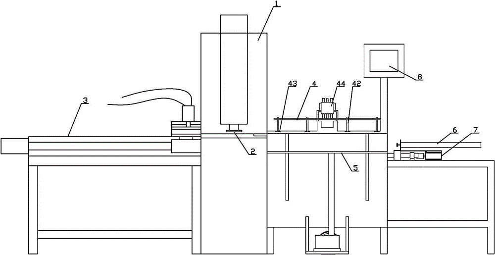
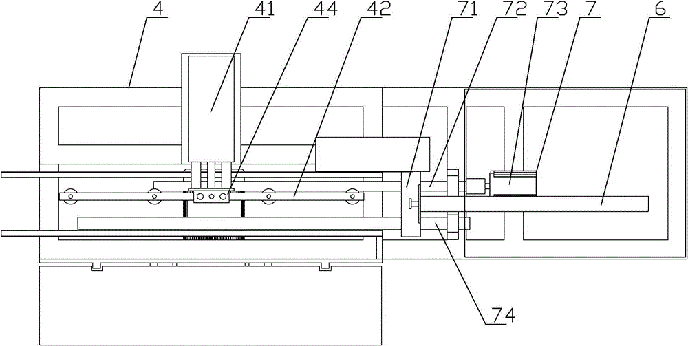
[0030] Such as Figure 1~5 Among them, a stamping automatic feeding device, including a pusher mechanism located on one side of the punching machine 1, the structure of the pusher mechanism is that the pusher plate 71 is fixedly installed on the piston rod of the pusher cylinder 6, and the pusher cylinder 6. Fixedly installed on the nut seat of the pusher ball screw 72, the nut seat of the pusher ball screw 72 is also slidably installed on the pusher guide rail 74, and the lead screw of the pusher ball screw 72 is connected with the pusher servo motor 73 , Pushing material servo motor 73 is fixedly installed on the frame, and the two ends of pushing material ball screw 72 and pushing material guide rail 74 are installed on the frame by supporting seat.
[0031] When in use, the plate-shaped material is placed on the material guide frame 9, and the piston rod of the material pushing cylinder 6 is stretched out to push the material to the initial processing position. The length...
Embodiment 2
[0045] A method for realizing automatic feeding by using the above-mentioned stamping automatic feeding device, comprising the following steps:
[0046] First push the material to the initial processing position with the material pushing cylinder 6, and then the material pushing servo motor 73 drives the material pushing plate 71 to push the material one processing station at a time, thereby realizing the automatic feeding of the material.
[0047] Optimally, the material on one side of the pushing cylinder 6 is transported to the pushing plate 71 and the material guide frame 9 by the feeding mechanism 4;
[0048] The steps are: the piston rod of the horizontal feeding cylinder 41 is stretched out, and when it is in place, the piston rod of the vertical feeding cylinder 44 is stretched out, the feeding rack 42 falls to the top of the material, the vacuum suction cup 43 sucks the material, and the vertical feeding cylinder 44 The piston rod is retracted, and the piston rod of t...
Embodiment 3
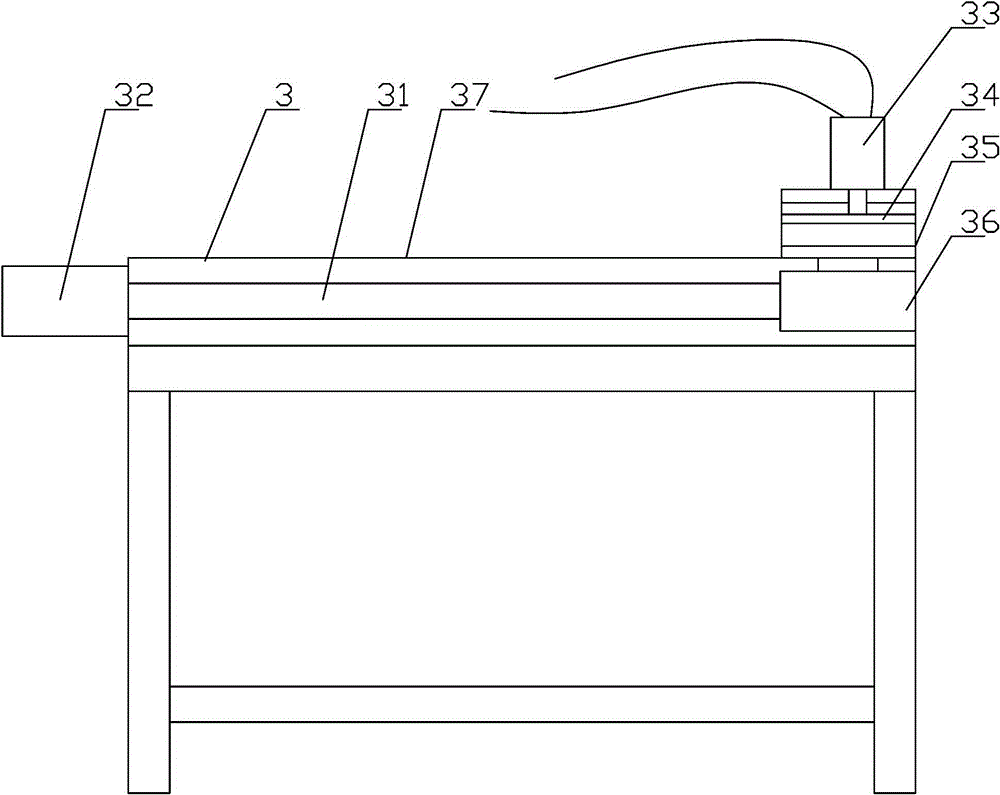
[0054] Such as figure 1 Among them, firstly, the feeding mechanism 4 sends the material to the pushing position through the vacuum suction cup, and the pushing cylinder quickly resets and takes the material and stops at the waiting position for feeding. Then the material is pushed to the left by the material pushing cylinder 6 of the material pushing mechanism to the material pushing servo ready position, and then the material is precisely positioned to the first processing position by the material pushing servo motor 73 through the material pushing ball screw 72, and punched by a punching machine , and then positioned to the second processing position by the pusher servo motor 73, when pushed to the fourth processing position, the material pulling mechanism 3 works, the material pulling cylinder 33 of the material pulling mechanism acts, and the pressure plate 34 clamps the upper left side of the material corner, and under the action of the pulling servo motor 32, accurately ...
PUM
 Abstract
Description
Claims
Application Information
 - R&D
- Intellectual Property
- Life Sciences
- Materials
- Tech Scout
- Unparalleled Data Quality
- Higher Quality Content
- 60% Fewer Hallucinations
Browse by: Latest US Patents, China's latest patents, Technical Efficacy Thesaurus, Application Domain, Technology Topic, Popular Technical Reports.
© 2025 PatSnap. All rights reserved.Legal|Privacy policy|Modern Slavery Act Transparency Statement|Sitemap|About US| Contact US: help@patsnap.com


