Improved opposite impact silencer

An improved muffler technology, applied in the direction of mufflers, machines/engines, engine components, etc., can solve the problems of weakening the effect of pressure offset, poor effect, and limited muffler effect, so as to improve the airflow buffering effect and muffle the noise Enhanced effect, fully hedged effect

Inactive Publication Date: 2014-09-17
马根昌
View PDF8 Cites 38 Cited by
  • Summary
  • Abstract
  • Description
  • Claims
  • Application Information

AI Technical Summary

Problems solved by technology

However, the technical effect of this technical solution is not very superior during the test process.
One of the reasons for the poor effect is that when the air mass is in the process of hedging, because there is an air outlet at the position of the hedging, the two air masses that are opposed to each other may have been squeezed into the air mass without being fully buffered. The air outlet, thus weakening the effect of the above-mentioned pressure offset; finally, the noise reduction effect is limited to a certain extent

Method used


Image

  • Improved opposite impact silencer
  • Improved opposite impact silencer

Examples


Embodiment 1

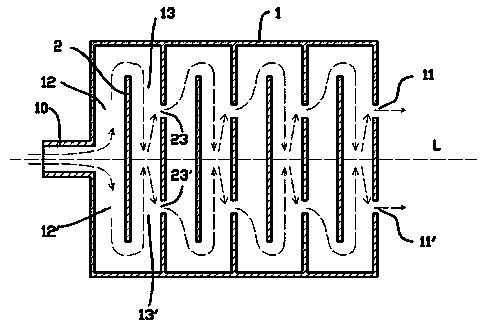
[0021] figure 1 Shown is the first embodiment of the muffler, wherein the muffler includes an air inlet 10, an exhaust port 11, 11'; the main part of the muffler is between the air inlet 10 and the air outlet 11, 11' , the main body part is surrounded by a flat cuboid metal cavity 1 .

[0022] Inside the metal cavity 1 , four splitting and hedging units connected end-to-end are separated by a partition plate 2 , and the internal channel structure of the splitting and hedging unit is also separated by the partition plate 2 .

[0023] Each of the splitting and countering units includes two splitting passages 12, 12' that symmetrically divide the intake air flow into two, and converging passages 13, 13 that merge the airflows in the two splitting passages 12, 12' facing each other. '; The channel walls of the two converging channels are respectively provided with air outlets 23, 23'; the air outlets 23, 23' are symmetrical about the confluence center of the air flow, that is, ab...

Embodiment 2

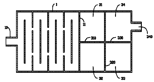
[0030] figure 2 Shown is the second embodiment of the muffler, which is different from the first embodiment in that: only one exhaust port 11 is provided on the last mentioned diversion and hedging unit, and a conventional muffler is connected through the exhaust port 11 body; the conventional muffling body includes four muffling chambers 31, 32, 33, 34, and each muffling chamber communicates with each other through mutually staggered airflow inlets and outlets 310, 320, 330; the air outlet of the last muffling chamber 34 340 is used as the exhaust port of the whole muffler; in order to further improve the muffler effect, muffler cotton can be arranged on the inner wall of each muffler cavity 31-34.

[0031] Due to the hedging and muffler in front of the conventional muffler, the exhaust noise of the engine has been weakened to a very weak level. In this case, the muffler cavity in the conventional muffler only needs a small volume to remove residual noise. Intersecting wit...


PUM


Abstract

The invention provides an improved opposite impact silencer. The improved opposite impact silencer comprises a gas inlet and an exhaust port, wherein more than one shunting opposite impact units which are connected end to end are arranged between the gas inlet and the exhaust port; each shunting opposite impact unit comprises two shunting passages which are used for symmetrically dividing the inlet flow into two, and confluence channels which are used for oppositely converging the gas flow in the two shunting passages from the front; gas outlets are respectively formed in the channel walls of the two confluence channels; the gas outlets are symmetrical about the converge center of the gas flow; each gas outlet is over 5 cm away from the converge center of the gas flow; the gas outlet of the previous shunting opposite impact unit is the gas inlet of the next shunting opposite impact unit. The improved opposite impact silencer has a smaller size, and has an excellent noise elimination effect compared with the patent application with application number 201210267691. 2.

Description

[0001] technical field [0002] The invention relates to the field of mufflers, in particular to a muffler for cylinder exhaust pipes. [0003] Background technique [0004] During the exhaust process of the engine cylinder, continuous pulse air pressure will be generated, and the pulse gas rushes out of the exhaust port at high speed. A muffler is installed on the air pipe to reduce noise. [0005] The current muffler mainly relies on the muffler chamber to eliminate noise. Generally, a muffler includes multiple muffler chambers, and the muffler chambers are connected through mutually staggered pipes. The sound chamber is repeatedly reflected and then discharged from the air outlet. During the repeated reflection of the noise airflow, the noise is absorbed by the muffler cotton on the inner wall of the anechoic chamber. [0006] For the current muffler, in order to achieve a good noise reduction effect, it is necessary to install a bulky noise reduction chamber. The larg...

Claims


Application Information

Patent Timeline
Patent Type & Authority Applications(China)
IPC IPC(8): F01N1/10
Inventor 马根昌
Owner 马根昌
Why Eureka
Try Eureka