Swirl combustion device for metal and water reaction

A combustion device and water reaction technology, applied in ramjet engines, mechanical equipment, etc., can solve the problems of insufficient chemical performance, low mixing efficiency of metal and water reaction, etc., to increase energy utilization rate, enhance combustion characteristics, The effect of improving working ability

Inactive Publication Date: 2014-09-17
HARBIN ENG UNIV
View PDF5 Cites 2 Cited by
  • Summary
  • Abstract
  • Description
  • Claims
  • Application Information

AI Technical Summary

Problems solved by technology

[0003] The purpose of the present invention is to provide a metal and water reaction vortex combustion device in order to make up for the low efficiency of the existing underwater engine metal and water reaction mixing, which cannot fully develop its chemical properties.

Method used


Image

  • Swirl combustion device for metal and water reaction
  • Swirl combustion device for metal and water reaction

Examples


Embodiment example 1

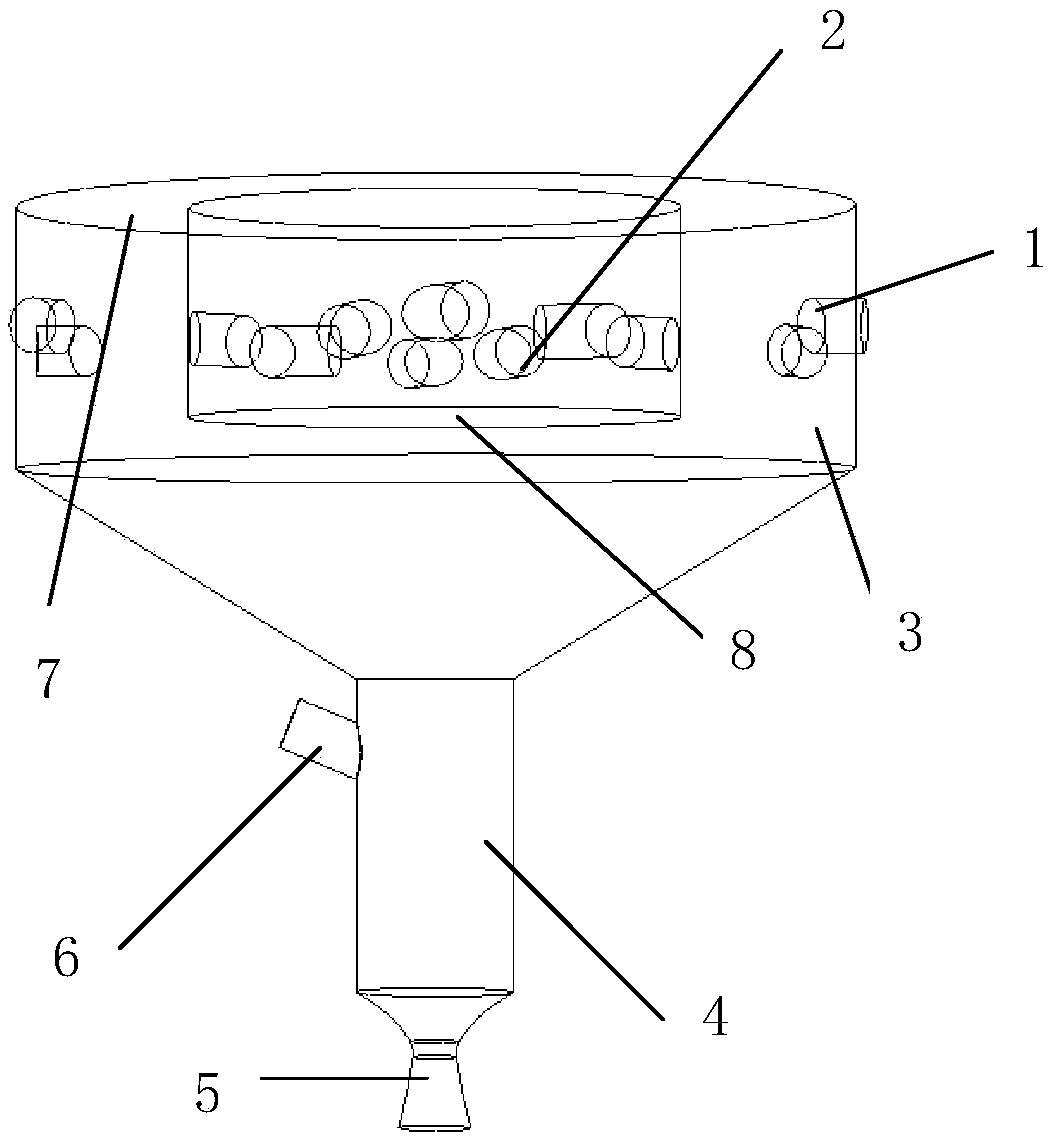
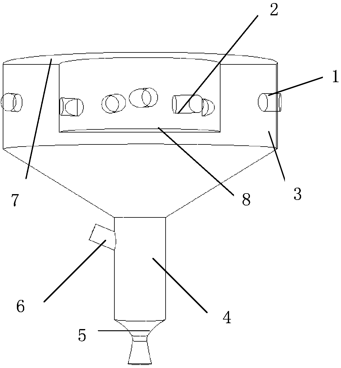
[0014] Implementation Case 1: Combining figure 1 , the vortex combustion device of the present invention includes a combustion chamber 3, the upper part of the combustion chamber 3 is a circular container, and the lower part is a conical container, and the circular container includes an outer wall, an inner wall, and a loam cake 7 connecting the inner wall and the outer wall and the bottom cover 8 surrounded by the inner wall, the outer wall of the circular container is provided with a metal nozzle 1, the inner wall of the circular container is provided with a water nozzle 2, the position of the water nozzle 2 corresponds to the position of the metal nozzle 1, and the upper part of the conical container is in line with the ring The lower end of the outer wall of the container is butted, and the bottom of the conical container is connected with the nozzle 5, and the nozzle 5 is in a gradually expanding shape. The upper end of the upper part of the annular container runs through...

Embodiment example 2

[0016] Implementation case two: according to the vortex combustion device described in the implementation case one, a secondary combustion chamber 4 is set at the bottom of the conical container, a secondary water injection nozzle 6 is arranged on the outer wall of the secondary combustion chamber 4, and the nozzle pipe 5 is connected to the secondary combustion chamber 6. The outlet location is connected.

[0017] Then the neutral gas and water vapor after the reaction in the combustion chamber will drive the incompletely reacted metal particles to move towards the outlet of the nozzle, first enter the secondary combustion chamber 4, and set an upper part of the secondary combustion chamber 4 The secondary water injection nozzle 6, the unreacted incompletely reacted metal particles and the water injected by the secondary water injection nozzle 6 carry out secondary combustion, the energy utilization rate increases, and the working ability of the fuel is also improved, so that ...


PUM


Abstract

The invention provides a swirl combustion device for metal and water reaction. The swirl combustion device for metal and water reaction comprises a combustion chamber, wherein the upper portion of the combustion chamber is an annular container, and the lower portion of the combustion chamber is a conical container. The annular container comprises an outer wall, an inner wall, an upper cover and a bottom cover, wherein the upper cover is used for connecting the inner wall and the outer wall, and the bottom cover is surrounded by the inner wall. A metal spray nozzle is arranged on the outer wall of the annular container, a water spray nozzle is arranged on the inner wall of the annular container, the position of the water spray nozzle corresponds to that of the metal spray nozzle, the upper portion of the conical container is in butt joint with the lower end of the outer wall of the annular container, and the bottom of the conical container is connected with a spray pipe. The swirl combustion device for metal and water reaction is simple in structure and reliable and can overcome the defect that because a compact oxidation film is formed on the surface of metal, combustion is affected; the diameter of molten metal liquid drops can be continuously reduced through shear force of swirls, the surface of unreacted metal is exposed so that the metal can react with water, and thus the metal and water reaction can go on stably, and the combustion efficiency of metal is improved.

Description

technical field [0001] The invention relates to a vortex combustion device, in particular to a vortex combustion device for reacting metal and water. Background technique [0002] Currently, the reaction of active metal particles and water is introduced into the propulsion system of underwater vehicles. However, the combustion efficiency of the combustion device of the traditional domestic underwater ramjet engine is not ideal. It can be found from the test that many solids remain inside the engine. The main reason for this result is the production of metal oxides, which wrap on the surface of metal particles and prevent the combustion from continuing. The traditional engine structure cannot complete the contact combustion of water vapor and metal particles well, which greatly reduces the reaction rate and affects the engine performance. Contents of the invention [0003] The purpose of the present invention is to provide a vortex combustion device for the metal and wate...

Claims


Application Information

Patent Timeline
IPC IPC(8): F02K7/10
Inventor 刘平安赵怡苗成林朱力邹高万王革
Owner HARBIN ENG UNIV
Why Eureka
Try Eureka