Gasoline vaporization device

A vaporization device and gasoline technology, which is applied to fuel heat treatment devices, charging systems, engine components, etc., can solve the problems of reducing the thermal efficiency of the engine, increasing the exhaust gas of the engine, and preventing the microscopic diameter of the oil mist from being small, so as to achieve a stable vaporization effect. , the effect of maintaining a stable temperature

Inactive Publication Date: 2014-09-17
韩志先
View PDF7 Cites 2 Cited by
  • Summary
  • Abstract
  • Description
  • Claims
  • Application Information

AI Technical Summary

Problems solved by technology

[0002] At present, the fuel supply system process of the known EFI gasoline engine is that the fuel pump passes the gasoline through the pressure oil delivery pipe at a certain pressure, passes through the fuel filter, the fuel pulsation attenuator, and the fuel pressure regulator, and the fuel injector turns the gasoline into Mist is supplied to the engine. Due to the limi

Method used


Image

  • Gasoline vaporization device
  • Gasoline vaporization device

Examples


Embodiment 1

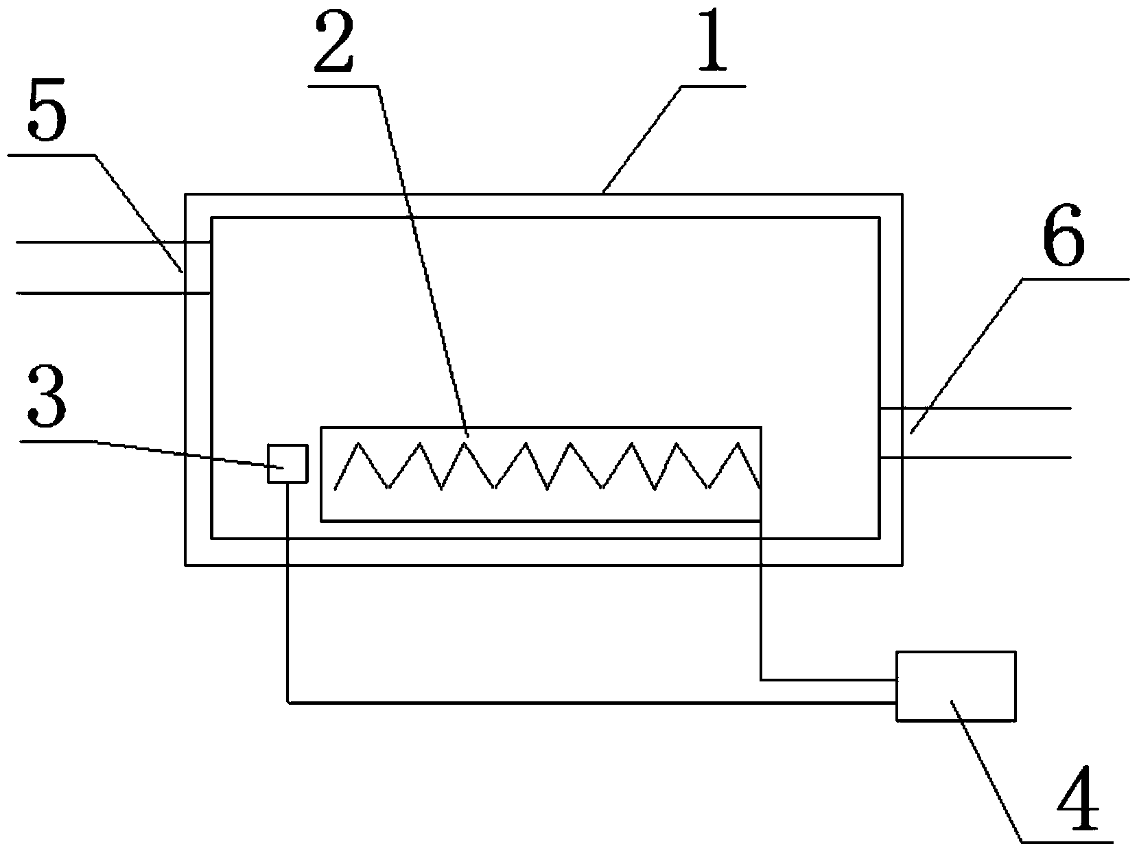
[0028] Example 1: Such as figure 1 As shown, gasoline enters the vaporization tank 1 from the pump oil pipe interface 6, and the gasoline is quickly vaporized under the heating action of the heater 2, and the vaporized gasoline enters the fuel injector from the fuel injection nozzle pipe interface 5; the temperature sensor 3 induces vaporization The temperature in the box 1 is transmitted to the temperature controller 4, and the temperature controller 4 regulates the power supply of the heater 2 according to the temperature sensor signal of the temperature sensor 3. If the temperature sensor signal shows the temperature in the vaporization box 1 If the temperature is too high, the temperature controller 4 stops supplying power to the heater 2. If the temperature sensing signal shows that the temperature in the vaporization box 1 is too low, the temperature controller 4 stops supplying power to the heater 2, thereby regulating the temperature in the vaporization box 1. Maintain s...

Embodiment 2

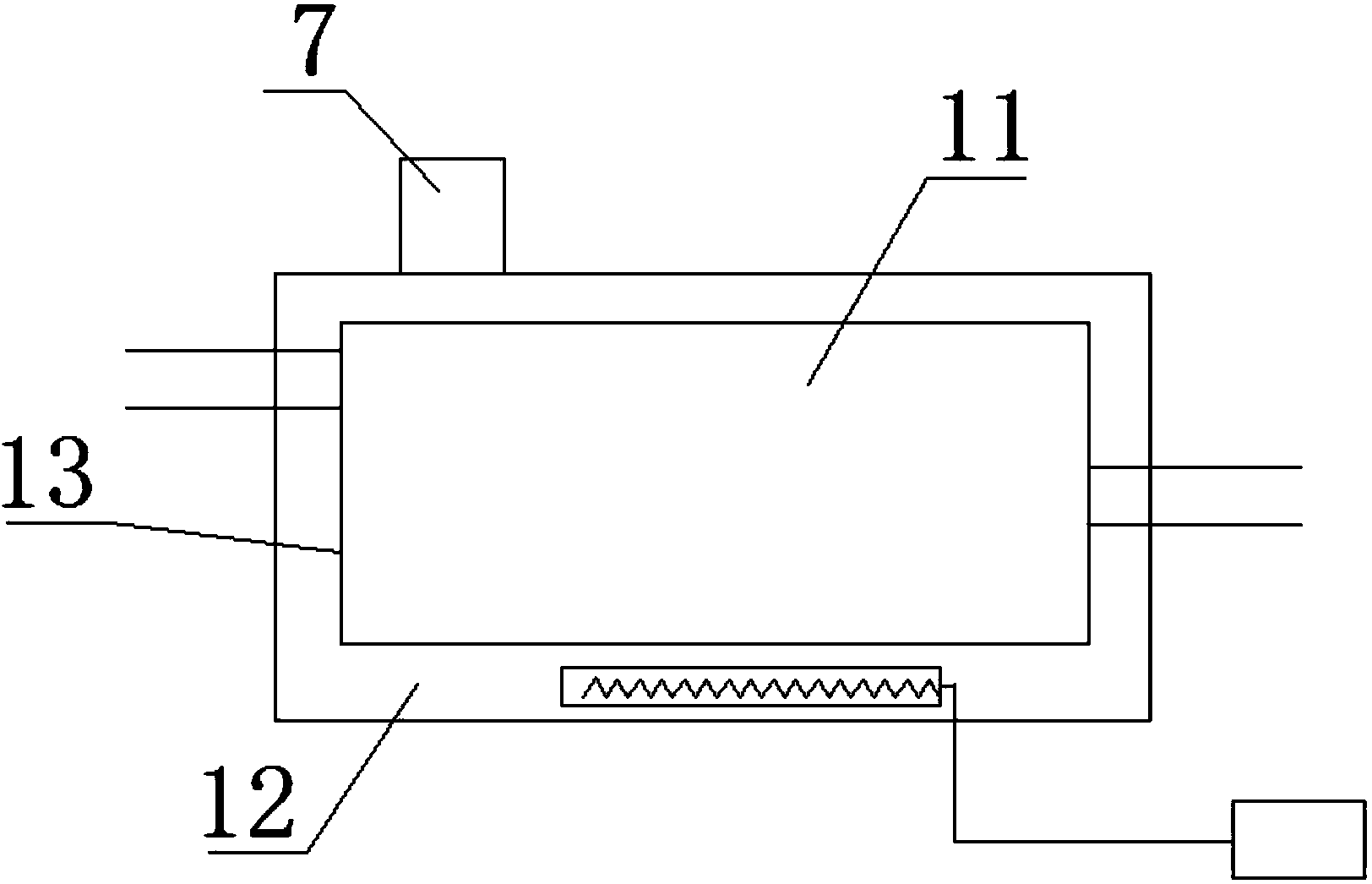
[0029] Embodiment 2: Gasoline is input into the first cavity 11 from the pump oil pipe interface 6, and the second cavity 12 is filled with a liquid with a larger specific heat capacity, and the liquid in the second cavity 12 is heated by the heater 2 to be heated The latter liquid transfers the heat to the first cavity 11 through the isolation plate 13, the gasoline is heated and vaporized in the first cavity 11. The vaporized gasoline enters the fuel injection nozzle from the fuel injection nozzle pipe interface 5, and the air pressure valve 7 can adjust the first cavity 11 The air pressure in the second cavity 12 makes the vaporization efficiency of gasoline high and stable, so that the combustion of gasoline is sufficient and safe, and the purpose of fuel saving is achieved.


PUM


Abstract

The invention relates to a gasoline vaporization device, which comprises a vaporization box, a heater, a temperature sensor and a temperature controller, wherein the heater is arranged at the bottom in the vaporization box, and is fixedly connected with the bottom of the vaporization box; the temperature sensor is arranged in the vaporization box; the temperature controller is connected with the temperature sensor and the heater respectively through lines. Compared with the prior art, the gasoline vaporization device has the advantages of simple structure, wide application range, high petroleum vaporization efficiency and stability and sufficient combustion of gasoline, and the aim of saving gasoline is fulfilled.

Description

Technical field [0001] The invention relates to the technical field of engine fuel supply, in particular to a gasoline vaporization device. Background technique [0002] At present, the well-known process of the fuel supply system of an EFI gasoline engine is that the fuel pump passes gasoline at a certain pressure through a pressure fuel pipe, passes through a fuel filter, a fuel pulsation attenuator, and a fuel pressure regulator, and then the gasoline is turned into The mist is supplied to the engine. Due to the limitation of the fuel vaporization mechanism, this fuel vaporization scheme cannot make the microscopic diameter of the oil mist required by the engine work smaller, so that the fuel is not fully burned in the engine, reducing the thermal efficiency of the engine and increasing engine waste. The concentration of carbon monoxide and hydrocarbons in steam emissions. Summary of the invention [0003] The technical problem to be solved by the present invention is to provi...

Claims


Application Information

Patent Timeline
IPC IPC(8): F02M31/18
Inventor 韩志先
Owner 韩志先
Why Eureka
Try Eureka