Device and method for supplying fuel or reducing agent, and plasma torch

A plasma and fuel supply technology, applied in the field of plasma torches, can solve problems such as the reduction of energy plasma density, and achieve the effects of suppressing the generation of soot, reducing energy consumption, and improving contact

Inactive Publication Date: 2007-12-26
TOYOTA JIDOSHA KK
View PDF4 Cites 5 Cited by
  • Summary
  • Abstract
  • Description
  • Claims
  • Application Information

AI Technical Summary

Problems solved by technology

However, when fuel is injected to the exhaust gas and plasma is provided during the subsequent exhaust gas treatment as in Unexamined Japanese Patent (Kokai) 2001-159309, the exhaust gas flow as a whole is converted into a plasma state, and thus in order to generate plasma Requires greater energy or reduced plasma density

Method used


Image

  • Device and method for supplying fuel or reducing agent, and plasma torch
  • Device and method for supplying fuel or reducing agent, and plasma torch
  • Device and method for supplying fuel or reducing agent, and plasma torch

Examples


Embodiment Construction

[0052] The present invention will be specifically described below based on the embodiments shown in the drawings, each of which is a diagram showing the principle of the present invention, but the present invention is not limited to these embodiments.

[0053]

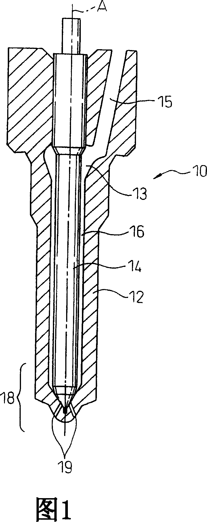
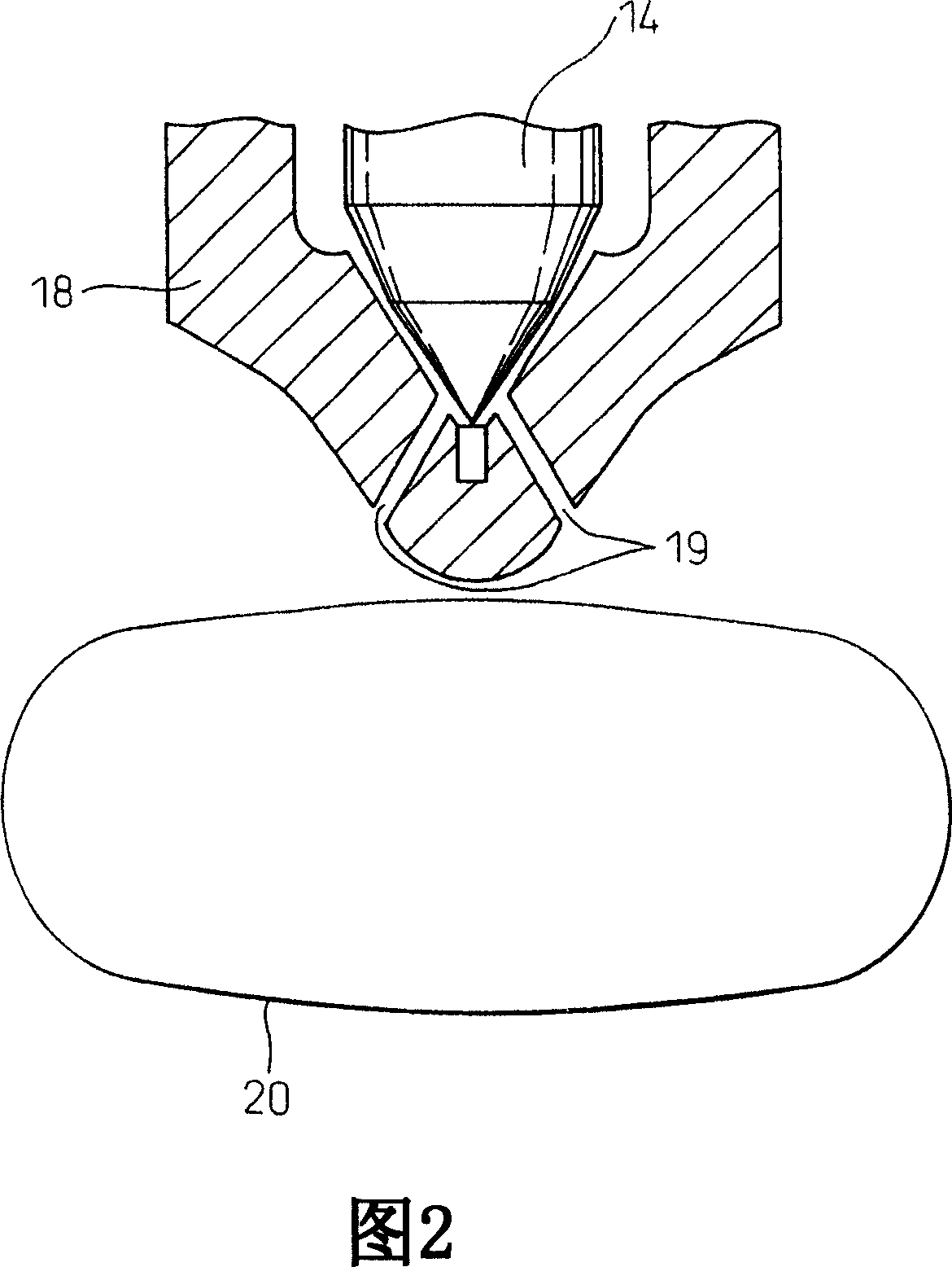
[0054] The device for supplying fuel or reducing agent of the present invention can be schematically described by referring to FIG. 2 .

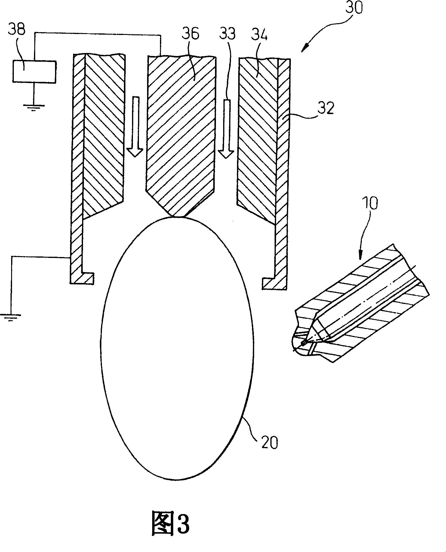
[0055] In the device for supplying fuel or reducing agent of the present invention, the fuel or reducing agent injected from the injector can be at least partially converted into plasma. As shown in FIG. 2 , this can be accomplished by injecting fuel or reducing agent from injection ports 19 located at the nozzle tip portion 18 into the plasma region, in particular, the plasma region 20 near the injection ports 19 .

[0056] The plasma region can be formed by converting gas such as nitrogen, air, argon, and recirculated exhaust gas into plasma, and then ejecting (supplying) the pla...


PUM


Abstract

The present invention provides an device and a method for supplying a fuel or a reducing agent, where a fuel or reducing agent supplied by injection can be vaporized and / or a fuel or reducing agent having high reactivity can be provided, and provides a plasma torch (30) usable therefor. The device for supplying a fuel or a reducing agent comprises a plasma torch (30) for converting a gas (23, 33) into a plasma and blowing out the plasma, and an injector (18) for injecting a fuel or a reducing agent to a region (20) where the plasma is supplied. The method comprises converting a gas (23 33) into a plasma, blowing out the plasma, and injecting a fuel or a reducing agent to the plasma region (20).

Description

technical field [0001] The invention relates to a device and a method for supplying fuel or a reducing agent, as well as a plasma torch that can be used in the device and method. Background technique [0002] Fig. 1 shows a conventional injector for injecting fuel directly into the combustion chamber of an internal combustion engine. 12 sliding (moving) in the hollow space. The nozzle 12 and the needle valve 14 are arranged such that their axes A extend coaxially. In addition, a supply passage 15 communicating with the hollow space 13 is provided in the nozzle 12 , the supply passage 15 is connected to a fuel source (not shown), and high-pressure fuel is supplied into the hollow space 13 through the supply passage 15 . The supplied fuel flows to the distal end portion 18 of the nozzle 12 through the annular passage 16 between the needle valve 14 and the inner wall surface of the nozzle 12 and is injected from the injection hole 19 at the distal end portion 18 of the nozzle...

Claims


Application Information

Patent Timeline
Patent Type & Authority Applications(China)
IPC IPC(8): F01N3/20F01N3/08F02M43/04B01D53/90F01N11/00
CPCF02M43/04F01N3/0814F01N3/0842F01N2240/28F01N2610/03F02B2275/14F02M25/022F02M25/03F02M25/0742F02M27/042Y02T10/121Y02T10/123F02M26/36Y02T10/12
Inventor 平田裕人松村惠理子石桥一伸
Owner TOYOTA JIDOSHA KK
Why Eureka
Try Eureka