Gas engine

A gas engine and fuel technology, which is applied to combustion engines, internal combustion piston engines, engine components, etc., can solve problems such as easy frosting and icing, affecting the normal operation of the fuel supply system, and deterioration of gaseous fuel vaporization quality

Inactive Publication Date: 2006-03-15
吕国怀 +2
View PDF0 Cites 4 Cited by
  • Summary
  • Abstract
  • Description
  • Claims
  • Application Information

AI Technical Summary

Problems solved by technology

But in the following two cases, it will not work normally: 1. Multiple pressure reducers are used in parallel on high-power gas engines: when two or more pressure reducers are used on high-power gas engines, such as each The mixer supplies fuel to each cylinder of the engine separately. It is impossible to make each pressure reducer consistent in terms of fuel vaporization, vaporized gas fuel pressure and density, etc., so that when the engine is working, the output of each cylinder of the engine The power is different, and the gas engine cannot work normally and stably; 2. Outboard engine: Outboard engine is a means of transportation used in lakes and offshore. Because the cooling system adopts external circulation, it uses gas fuel When using the warm water in the engine cooling system for fuel vaporization required by gaseous fuels, it will have a greater impact
When the engine is running at idle speed, the cooling water in the engine will decrease rapidly with the increase of idle running time, which will make the vaporization quality of gas fuel worse
Especially in the gas continuous injection system, the actuator on the fuel distributor --- the stepper motor, is installed in the hanger cover, and cannot be used when the engine is running under heavy load (so the fuel is in gas-liquid two-phase supply). The air takes away the cold air accumulated on the stepping motor, resulting in easy frosting and icing, which affects the normal operation of the fuel supply system

Method used


Image

  • Gas engine
  • Gas engine
  • Gas engine

Examples


Embodiment Construction

[0011] The present invention will be further described below in conjunction with the accompanying drawings and embodiments.

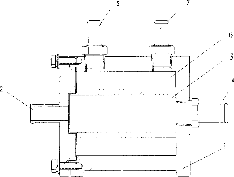
[0012] See attached figure 1 , the secondary vaporizer 1 described in the present embodiment is composed of two mutually closed and thermally contacted water and gas pipelines, the water inlet and outlet interfaces 2 and the water chamber 3 and the water inlet and outlet 4 constitute the water pipeline, the air inlet and outlet 5 and the air chamber 6 and the gas inlet and outlet 7 form a gas pipeline, and water and gas go their own way in the secondary vaporizer 1 and can perform heat exchange.

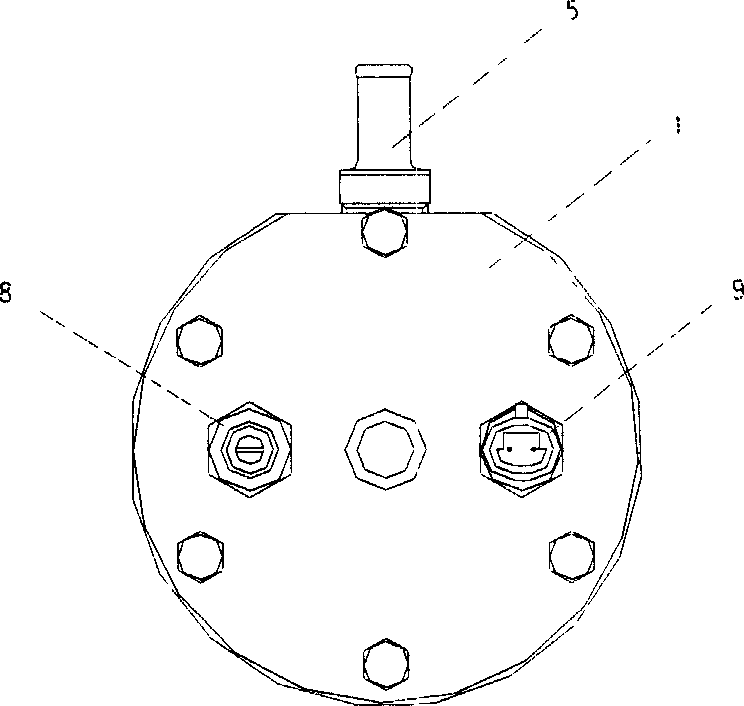
[0013] See attached figure 2 , the electric heating tube 8 and the temperature sensor 9 are installed on one wall of the secondary vaporizer 1, and are respectively connected with the control unit of the gas engine, and when the temperature sensor 9 detects that the gas in the air chamber 6 is too low, a signal is sent to the control unit , the control unit...


PUM


Abstract

A gas engine using LPG or natural gas as fuel supply has a secondary vaporizer in between the reducer and distributor. The secondary vaporizer is comprised by a sealed water pipe and a sealed gas pipe which are connected side by side. On the secondary vaporizer may install a heating system and temperature sensor. The engine of this kind of structure is characterized of balanced gas distribution in each cylinder and stable running.

Description

technical field [0001] The invention relates to a gas engine, in particular to a gas engine using liquefied petroleum gas and natural gas as fuel. Background technique [0002] To meet the needs of national environmental protection and fuel structure adjustment, gas engines are the main way of power in road and water transportation. [0003] The fuel supply system of the gas engine currently used in my country is divided into a negative pressure system and a positive pressure system, which are mainly composed of a fuel gas cylinder, a pressure reducer, a control unit, a wiring harness, a fuel display, a distributor (injection system) and a nozzle. In general, it can be used normally. But in the following two cases, it will not work normally: 1. Multiple pressure reducers are used in parallel on high-power gas engines: when two or more pressure reducers are used on high-power gas engines, such as each The mixer supplies fuel to each cylinder of the engine separately. It is ...

Claims


Application Information

Patent Timeline
Patent Type & Authority Applications(China)
IPC IPC(8): F02M21/06
CPCY02T10/32Y02T10/30
Inventor 吕国怀李健周建清
Owner 吕国怀
Why Eureka
Try Eureka