Urea mixing device

A mixing device and urea technology, which is applied in the direction of muffler, exhaust device, exhaust treatment, etc., can solve the problems of low crystallization risk of gas flow rate distribution uniformity, poor gas flow rate distribution uniformity, urea crystallization, and poor mixing uniformity, etc., to achieve Good mixing effect, high mixing uniformity, good swirling effect

Pending Publication Date: 2020-02-28
无锡亿利环保科技有限公司
View PDF0 Cites 4 Cited by
  • Summary
  • Abstract
  • Description
  • Claims
  • Application Information

AI Technical Summary

Problems solved by technology

[0004] Aiming at the disadvantages of poor gas flow velocity distribution uniformity, easy formation of urea crystallization and poor mixing uniformity in the existing tail gas post-treatment mixer, the applicant provides a peanut shell type urea mixing device with reasonable structure, which has high gas flow velocity distribution uniformity and crystallization Low risk, high mixing uniformity

Method used


Image

  • Urea mixing device
  • Urea mixing device
  • Urea mixing device

Examples


Embodiment Construction

[0041] The specific implementation manner of the present invention will be described below in conjunction with the accompanying drawings.

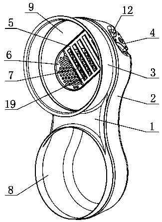
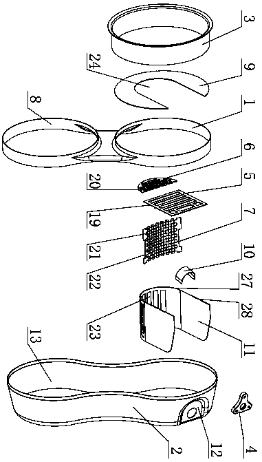
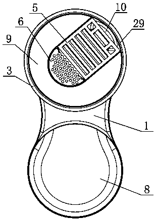
[0042] Such as figure 1 As shown, the front shell 1 of the present invention is fixed on the rear shell 2, and an internal cavity 13 is formed between the front shell 1 and the rear shell 2, and the left and right sides of the middle part of the front shell 1 and the rear shell 2 respectively face the internal cavity 13 is concave inward to form a waist structure, and the overall cross-section of the present invention along the longitudinal axis is in the shape of a peanut shell. The upper part of the front housing 1 is equipped with an air intake cylinder 3 , and the lower part has a cylindrical air outlet 8 , and the air intake cylinder 3 and the air outlet 8 communicate with the internal cavity 13 . Such as figure 2 As shown, a U-shaped partition 11 is fixed between the front casing 1 and the rear casing 2, and the partition 11 inclu...


PUM


Abstract

The invention discloses a urea mixing device. A partition is arranged between a front housing and a rear housing, a breaking plate is fixed to the partition, a front baffle is arranged on the front end part of the partition, an opening is formed in a part corresponding to the partition, of the front baffle, a flow guide plate and a hole plate are arranged on the opening, and an intake port is formed between the flow guide plate and an inner wall surface corresponding to the front housing; a blade opened inwards and towards an injection cavity is formed in the flow guide plate; a plurality of first through holes are formed in the hole plate; grating openings are formed in a wall surface facing the breaking plate, of the partition; and the rear housing is provided with a waist-reducing part.According to the urea mixing device, the plurality of grating openings are formed in the part facing the breaking plate, of the partition, and play a role of secondary breaking on urea drops, and more thorough atomization and volatilization for the urea drops are ensured, so that adequate mixing for mixed gas flow is much benefited, and higher mixing uniformity is achieved. The rear housing is provided with the waist-reducing part, and the flowing speed of the mixed gas flow while passing through the waist-reducing part, is increased, so that a better mixing effect and higher mixing uniformity are achieved.

Description

technical field [0001] The invention relates to the technical field of automobile exhaust post-treatment, in particular to a urea mixing device. Background technique [0002] The automobile exhaust after-treatment device belongs to the engine exhaust system, and its main function is to reduce the nitrogen oxides (NO X ), hydrocarbons (CH), carbon monoxide (CO) and other harmful gases are converted into environmentally friendly nitrogen (N 2 ) and water (H 2 O) etc. At present, DOC (oxidizing catalyst) + DPF (particulate filter) + SCR (selective catalytic reduction) technology is often used in diesel engines to post-treat exhaust emissions, and the atomization and mixing effects of urea aqueous solution in post-treatment, It has a great influence on the selective reduction reaction in the subsequent SCR. Improving the uniformity of mixing urea and exhaust gas in the mixer is the key to improving the conversion efficiency of aftertreatment. [0003] Existing exhaust gas po...

Claims


Application Information

Patent Timeline
Patent Type & Authority Applications(China)
IPC IPC(8): F01N3/28F01N3/20F01N5/02
CPCF01N3/2006F01N3/2066F01N3/2892F01N5/02F01N2610/02F01N2610/1453Y02T10/12
Inventor 苏赵琪田入园李江飞冯玉杰朱海艳牛雨飞
Owner 无锡亿利环保科技有限公司
Why Eureka
Try Eureka