
Vibration detection in thermowells

A thermowell, vibration signal technology, applied in the direction of vibration measurement in solids, measuring vibration, thermometers with directly sensitive electrical/magnetic components, etc., can solve problems such as increasing the possibility of resonance conditions

Active Publication Date: 2014-09-17
ROSEMOUNT INC
View PDF9 Cites 7 Cited by
  • Summary
  • Abstract
  • Description
  • Claims
  • Application Information

AI Technical Summary

Problems solved by technology

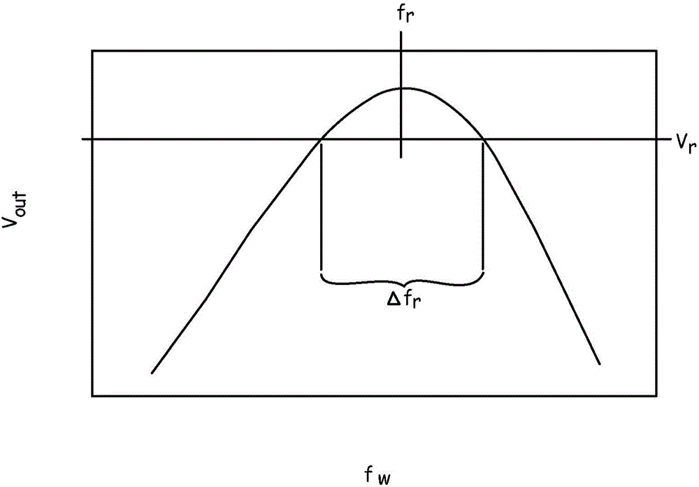
However, over the life of the thermowell, changes in process conditions can cause f w and / or f r shift, increasing the likelihood of a resonant condition

Method used


Image

  • Vibration detection in thermowells
  • Vibration detection in thermowells
  • Vibration detection in thermowells

Examples


Embodiment Construction

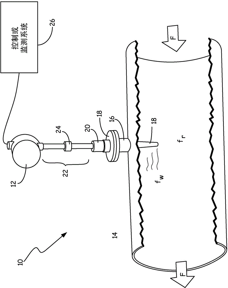
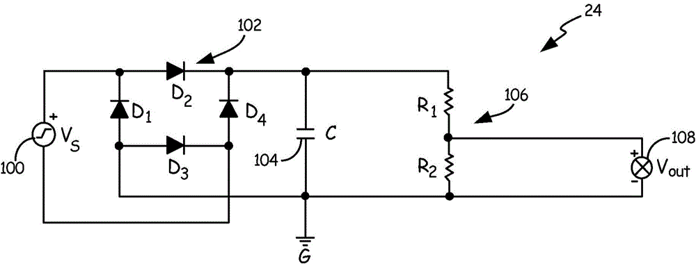
[0009] figure 1 is a simplified cross-sectional view of one embodiment of a process system 10 (a system for monitoring and / or stimulating an industrial fluid process). In the depicted embodiment, process system 10 includes process transmitter 12, process piping 14 (with flanged connection 16), thermowell 18, process transducer 20, extension 22, vibration sensor 24, and control Or monitoring system 26 .

[0010] Process line 14 carries process stream F for an industrial process. Process lines 14 may be, for example, tubes or ducts configured to carry fluids, such as oil slurries, viscous manufacturing materials, gases, or liquids. Process line 14 includes at least one flange connection 16 to facilitate connection of flange-mounted equipment to measure at least one characteristic of process flow F, such as temperature, flow rate, pressure, or pH. In the illustrated embodiment, flange connection 16 provides an attachment point for thermocouple well 18 and process transducer 20...


PUM


Abstract

A sensor system comprises a process transducer, an unpowered vibration sensor, and a process transmitter. The process transducer is disposed within a thermowell and configured to produce a first sensor signal. The unpowered vibration sensor is configured to produce a second sensor signal reflecting vibration of the thermowell. The process transmitter is configured to receive, process, and transmit the first and second sensor signals.

Description

technical field [0001] The present invention relates generally to process sensor systems, and more particularly to thermowell sensor housings for fluid sensors in industrial process monitoring systems. Background technique [0002] Industrial process transmitters and sensor assemblies are used to sense various characteristics of process fluids flowing through conduits or contained within vessels, and to send information related to those process characteristics to controls, Monitoring and / or security systems. Each process transmitter may be connected to one or more sensor and / or actuator components. Sensor assemblies can sense many process parameters, including pressure, temperature, pH, or flow rate. Process transmitters are typically sensor assemblies electrically connected via sensor wires for transmitting a current or voltage based analog sensor output signal reflecting at least one such process parameter. Each transmitter reads these sensor output signals and converts...

Claims


Application Information

Patent Timeline
IPC IPC(8): G01H11/06G01K7/02G01K7/16
CPCG01K1/024G01H1/00G01K13/02G01H11/06G01H13/00G01K1/08
Inventor 劳伦·迈克尔·安格斯塔德杰森·哈洛德·鲁德
Owner ROSEMOUNT INC
Learn More