
Passive positioning technology based on difference measurement

A technology of relative measurement and positioning method, applied in positioning, measurement device, radio wave measurement system and other directions, can solve the problems of measurement ambiguity, high repetition frequency signal positioning ambiguity, echo pulse cannot be matched, etc. The effect of simple detection method and high measurement accuracy

Inactive Publication Date: 2014-09-17
郁涛
View PDF0 Cites 21 Cited by
  • Summary
  • Abstract
  • Description
  • Claims
  • Application Information

AI Technical Summary

Problems solved by technology

[0006] 2. The distance between stations must be long enough
For this reason, in actual engineering, the station layout and addressing of the time difference positioning system is often a relatively difficult task
[0007] 3. Positioning ambiguity for high repetition frequency signals
High repetition rate pulses cause measurement ambiguity and leave a few echo pulses unpaired during the identification process

Method used


Image

  • Passive positioning technology based on difference measurement
  • Passive positioning technology based on difference measurement
  • Passive positioning technology based on difference measurement

Examples


Embodiment

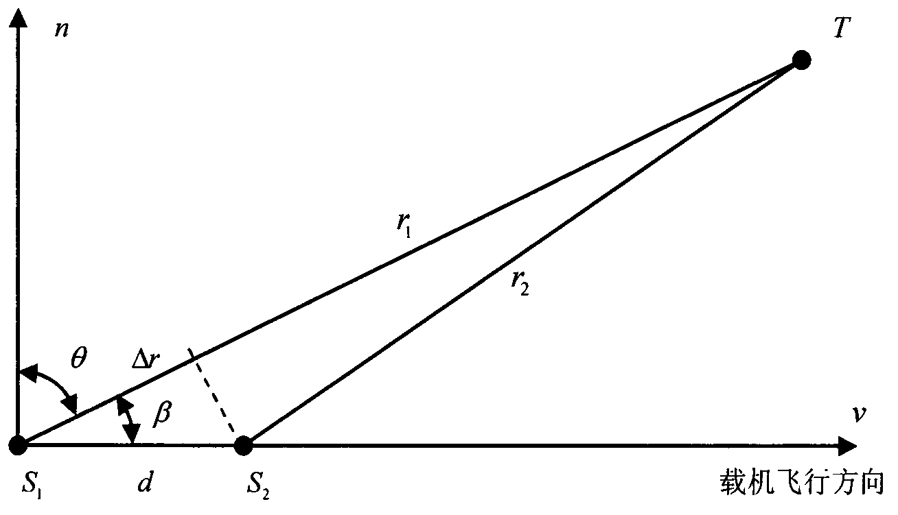
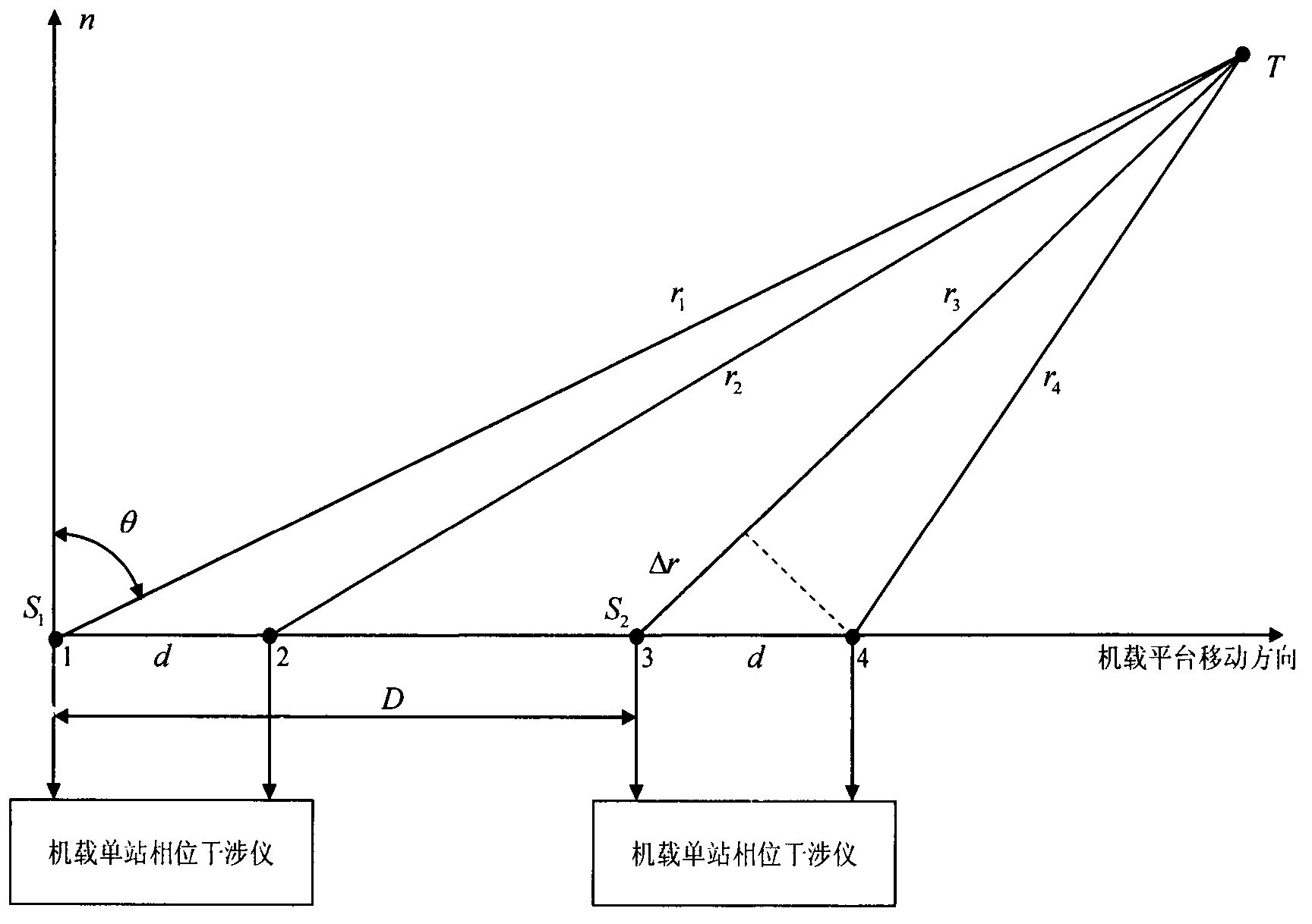
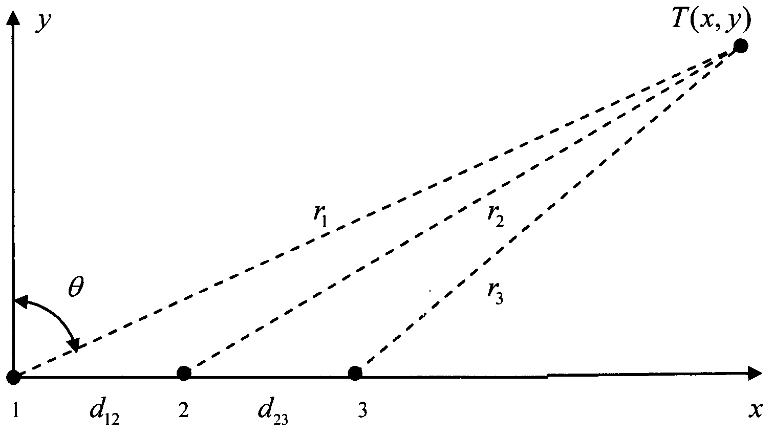
[0046] A passive positioning method based on phase measurement technology to detect the target distance. figure 1 is a schematic diagram of the airborne single baseline array; figure 2 is the schematic diagram of airborne multi-point ranging; image 3 It is a one-dimensional two-base three-antenna non-uniform phase interference direction-finding array; Figure 4 is the geometric schematic diagram of path difference correction; Figure 5Described the schematic diagram of dual-station phase difference passive positioning; Figure 6 is the relative calculation error curve at different inter-station distances; Figure 7 is the relative measurement error curve at different distances between stations; Figure 8 Relative measurement errors are given for different array short baseline lengths.

[0047] The solution proposed by the present invention starts from the research on airborne Doppler direct ranging method [(1) Yu Tao. Airborne ranging method based on angle change rate [...


PUM


Abstract

The invention discloses a method for realizing high-precision distance measurement through measuring a phase difference. First of all, by use of a function relation between a phase shift and a frequency shift, an airborne distance measurement formula led out from a Doppler equation is converted to a method for positioning a fixed object by an airborne single station only on the basis of the difference measurement. Based on this, on one hand, based on a characteristic that an airborne difference distance measurement solution is irrelevant to the motion speed of a detection platform itself, and on the other hand, through comparing with an approximate expression, obtained through derivation based on a difference positioning equation, of a strict distance measurement solution, an airborne difference passive distance measurement method is further developed to a double-station positioning method which is not only restricted to motion states of the platform itself, but also can perform real-time detection on maneuvering objects. Since error measuring equation of the difference distance measurement solution is irrelevant to a huge-magnitude light velocity, compared to a time difference positioning technology, better positioning precision can be obtained through fewer sites by use of difference positioning. A result given by use of the method definitely explores a new research direction for the development of a positioning technology.

Description

technical field [0001] The invention belongs to the technical field of radio positioning measurement, and in particular relates to a method for realizing long-distance and high-precision distance measurement by applying phase difference measurement technology. Background technique [0002] Passive positioning itself does not emit signals. It obtains the position and parameter information of the target through the search, measurement and processing of the electromagnetic signal radiated by the target, and further obtains the track of the target. Passive positioning has the characteristics of long range and good concealment. Under the current technical conditions, multi-station passive positioning technology is still a more effective long-distance passive detection and positioning method. Among them, the time difference positioning system has become a main direction of passive system development because of its advantages such as good positioning accuracy and high spatial reso...

Claims


Application Information

Patent Timeline
Patent Type & Authority Applications(China)
IPC IPC(8): G01S5/02
CPCG01S5/02
Inventor 郁涛
Owner 郁涛
Learn More