Automatic stereoscopic warehouse demonstration teaching aid box
A technology of three-dimensional warehouses and teaching aids, applied in the field of teaching aids, can solve the problems of unrealistic cognition of mechanical principles and operation methods, lack of teaching models, and difficult operating procedures for students, so as to achieve easy teaching, easy movement, and high degree of automation Effect
- Summary
- Abstract
- Description
- Claims
- Application Information
AI Technical Summary
Problems solved by technology
Method used
Image

Examples
Embodiment Construction
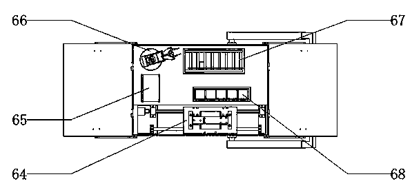
[0021] An automatic three-dimensional warehouse demonstration teaching aid box, comprising: a pallet shelf 68 and a double-column roadway stacker 64 are installed on the inner bottom plate of the box body 47, and a roller conveyor 67, a loading platform 65 and a manipulator are installed on the other side bottom plate 66.
[0022] Described box body 47, the bottom of box body 47 is equipped with wheel 46, and side wall is equipped with pull bar 52, and box body 47 is made up of each box surface and box body cover 49 by seamless page 51 connection, and limit position is also set on the box body. device 48, a control layer 50 is arranged inside the box body, and a lifting mechanism 71 is arranged inside the box body. The overall case is compact, light in weight and easy to carry.
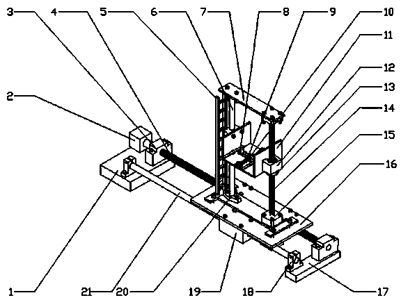
[0023] The described double-column roadway stacker 64 includes: a left base plate 1, a motor 2 and a left support base 3 are installed above the left base plate 1, and one end of the lead screw 4 pas...
PUM
 Abstract
Description
Claims
Application Information
PatSnap Eureka turns technology decisions into work you can execute. Powered by our Innovation Knowledge Graph, it runs expert workflows across engineering, life sciences, materials and intellectual property. Get your review-ready output in minutes.


