Microfluid control device and method of manufacturing the same

An electro-optical device and driving method technology, applied in optics, nonlinear optics, instruments, etc., can solve problems such as long-term reliability impact

Inactive Publication Date: 2014-09-17
SEIKO EPSON CORP
View PDF7 Cites 9 Cited by
  • Summary
  • Abstract
  • Description
  • Claims
  • Application Information

AI Technical Summary

Problems solved by technology

Therefore, there is a problem that, when the pixel is repeatedly driven in a state where the DC balance is broken, even if the color of the pixel is to be displayed using the predetermined driving waveform data, color deviation or the like may be seen. Issues that negatively impact long-term reliability

Method used


Image

  • Microfluid control device and method of manufacturing the same
  • Microfluid control device and method of manufacturing the same
  • Microfluid control device and method of manufacturing the same

Examples


no. 1 approach

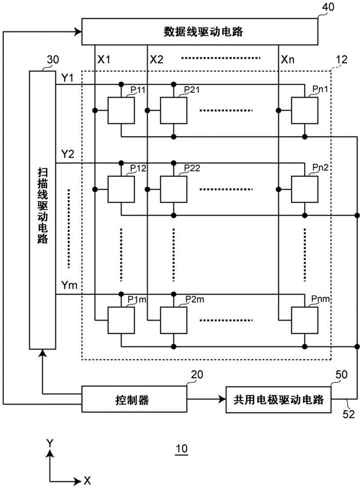
[0066] exist figure 1 A block diagram of a configuration example of an electrophoretic display device as an electro-optical device according to the first embodiment of the present invention is shown in .

[0067] The electrophoretic display device 10 according to the first embodiment includes a display element having memory in each pixel, and has a property of maintaining a previous display state without updating the display state. This electrophoretic display device 10 includes a pixel area 12 , a controller 20 , a scanning line driving circuit 30 , a data line driving circuit 40 and a common electrode driving circuit 50 . Some or all of the scanning line driving circuit 30 , the data line driving circuit 40 , and the common electrode driving circuit 50 function as a driving device for the electrophoretic display device 10 . Alternatively, you can figure 1 The part of the pixel area 12 is used as an electrophoretic display device, and a controller 20, a scanning line drivin...

no. 2 approach

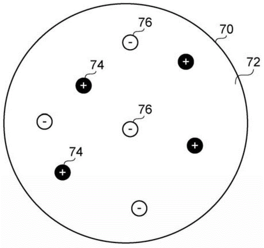
[0108] In the first embodiment, an example in which the microcapsule 70 has the solvent 72 and the electrophoretic particles 74 and 76 and is controlled by two driving voltages has been described, but the embodiments of the present invention are not limited thereto. In the second embodiment, the microcapsule and the solvent have a plurality of electrophoretic particles with mutually different threshold values, and are controlled with four driving voltages. Hereinafter, for the convenience of description, in the second embodiment, differences from the first embodiment will be described.

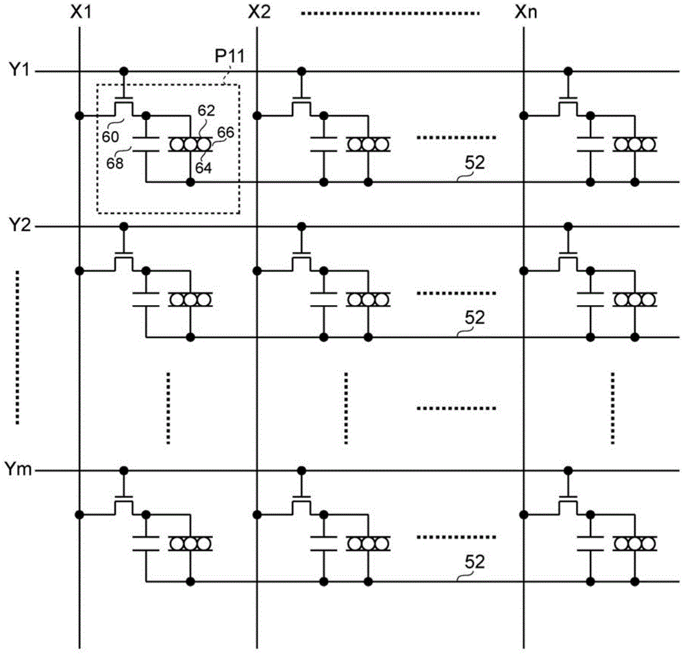
[0109] exist Figure 9 , the outline of the configuration of the microcapsules constituting the electrophoretic element in the second embodiment is shown. In the second embodiment, figure 2 The electrophoretic element 66 consists of Figure 9 Microcapsules 170 are shown.

[0110] The microcapsule 170 in the second embodiment has an uncolored and viscous solvent 172 , a plurality of electr...

no. 3 approach

[0131] Embodiments of the present invention are not limited to the first embodiment or the second embodiment. In the third embodiment, the microcapsule has a solvent and a plurality of electrophoretic particles having different threshold values, and is controlled by eight driving voltages. Hereinafter, for convenience of description, in the third embodiment, differences from the first embodiment will be described.

[0132] exist Figure 16 , the outline of the configuration of the microcapsules constituting the electrophoretic element in the third embodiment is shown. In the third embodiment, figure 2 The electrophoretic element 66 consists of Figure 16 Microcapsules 270 are shown.

[0133] The microcapsule 270 in the third embodiment includes a viscous solvent 272 colored in black, a plurality of electrophoretic particles 274 colored in red, a plurality of electrophoretic particles 276 colored in green, and a viscous solvent 272 colored in blue. A plurality of electrop...


PUM


Abstract

Provided are a plastic microfluid control device having a multi-step microchannel and a method of manufacturing the same. The device includes a lower substrate, and a fluid channel substrate contacting the lower substrate and having a multi-step microchannel having at least two depths in a side coupling to the lower substrate. Thus, the device can precisely control the fluid flow by controlling capillary force in a depth direction of the channel by controlling the fluid using the multi-step microchannel having various channel depths. A multi-step micropattern is formed by repeating photolithography and transferred, thereby easily forming the multi-step microchannel having an even surface and a precisely controlled height.

Description

technical field [0001] The invention relates to a driving method of an electro-optic device, a driving device of the electro-optic device, the electro-optic device, electronic equipment and the like. Background technique [0002] Conventionally, as an example of such an electro-optical device, an electrophoretic display device is known. The electrophoretic display device has a structure in which an electrophoretic element including colored electrophoretic particles is sandwiched between a pixel electrode and a counter electrode, and an image is displayed by electrophoresis by applying a voltage between the electrodes to cause the electrophoretic particles to migrate. In this case, in the electrophoretic display device, for example, when electrophoretic particles colored in different colors are independently controlled to migrate for each color, it becomes possible to change the color of the displayed image. The electrophoretic element is composed of, for example, a pluralit...

Claims


Application Information

Patent Timeline
Patent Type & Authority Applications(China)
IPC IPC(8): G09G3/34G02F1/167
CPCG09G2310/068G09G3/344G09G2310/065G09G2320/0204G09G2310/061G09G3/2003
Inventor 小川英树藤森啓太郎
Owner SEIKO EPSON CORP
Why Eureka
Try Eureka